Golf putter and counterbalance system and fitting method

a technology of a counterbalance system and a putter, which is applied in the field of golf clubs, can solve the problems that mirrors cannot be used in competition play as sanctioned, and achieve the effects of improving accuracy and repeatability, speeding up the learning process, and improving the player's gam

Inactive Publication Date: 2011-04-21
LEE MICHAEL +1
View PDF22 Cites 10 Cited by
  • Summary
  • Abstract
  • Description
  • Claims
  • Application Information

AI Technical Summary

Benefits of technology

[0024]The golf putters and methods described above permit the experienced golfer to improve his game and speeds up the learning process for an amateur by aiding the golfer to learn the necessary angularity and distance requirements between the striking face of the putter, the golf ball and the cup on the green, as well as the proper pendulum swing for true and accurate play. The customization of the golf putter to the individual go

Problems solved by technology

It must be recognized however that attachments, such as mirrors, cannot be used in competition play as sanctioned by the United

Method used


Image

  • Golf putter and counterbalance system and fitting method
  • Golf putter and counterbalance system and fitting method
  • Golf putter and counterbalance system and fitting method

Examples


example 1

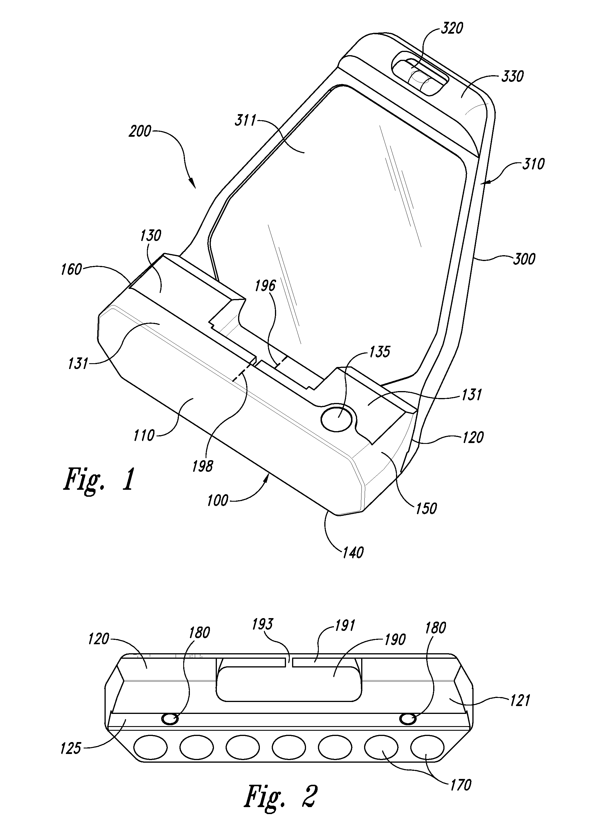
[0085]Referring to FIG. 1, the putter head 100 has golf ball striking face 110, a rearward face 120, a top surface 130, a bottom surface 140, a heel region 150 and a toe region 160. The top of the putter head may comprise a substantially horizontal surface with one or more parallel machined steps 131. The putter head further includes an opening 135 into which a golf club shaft may be inserted.

[0086]Referring to FIG. 2, the rearward face 120 has a mounting face 121 with female groove 125 extending across the mounting face in the heel 150 to toe 160 direction. Putter head 100 further comprises bores 170 and threaded apertures 180.

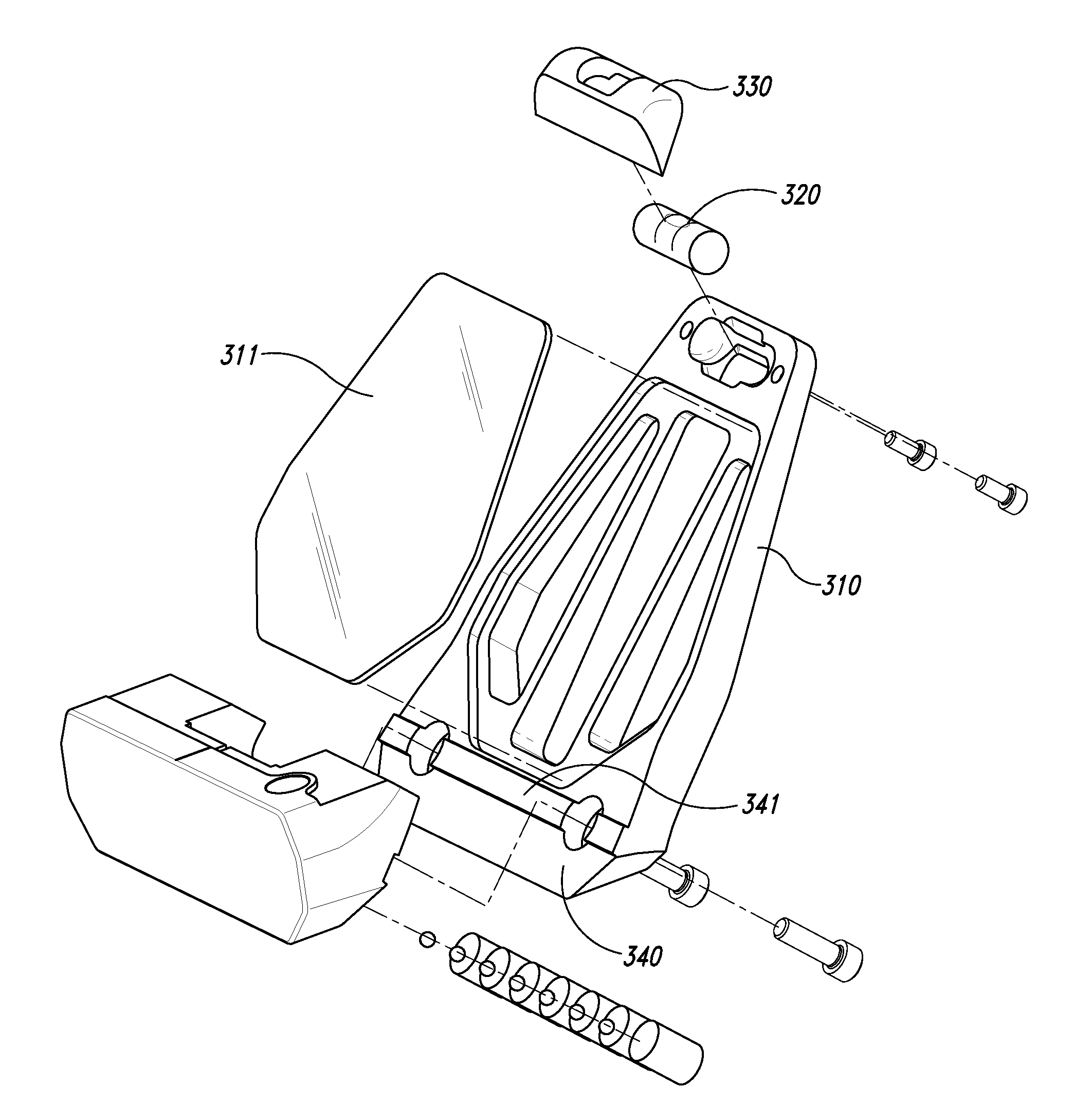
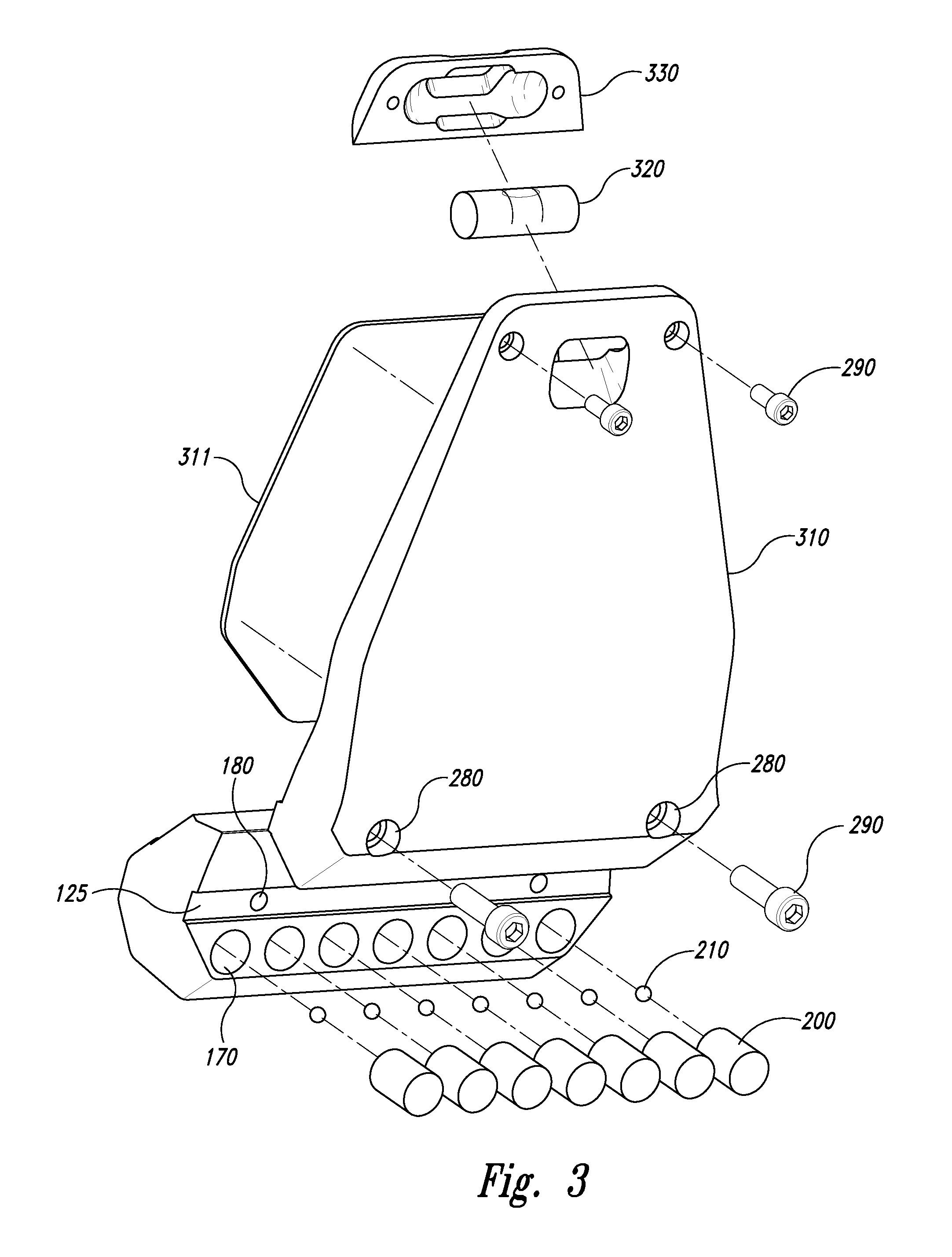
[0087]Referring to FIG. 3, weights 200 are shown. The weights 200 are made from brass, tungsten or steel. Rubber balls 210 are inserted into bores 170 before weights 200 are inserted. Referring to FIG. 4, the weights 200 are retained within bores 170 by mirror attachment 300 when the attachment is fitted to putter head 100.

example 2

[0088]Referring to FIGS. 1 and 5, the putter head 100 is interconnected to mirror attachment 300. Mirror attachment 300 comprises a frame 310, mirror 311, a bubble level 320, and a removable frame 330 for retaining the bubble level. The frame 310 comprises mounting face 340 with a male feature 341 that matches the female groove 125 of putter head 100. Referring to FIG. 3, apertures 280 match apertures 180 of putter head 100 so that hex-head fasteners 290 can interconnect mirror attachment 300 and putter head 100. Hex head fasteners are also used to attach level frame 330 to mirror frame 310. Apertures 280 are further bored to permit the head of fasteners 290 to recess inside frame 310.

example 3

[0089]Referring to FIGS. 2 and 6, putter head 100 has rear central recess 190. Rear central recess 190 includes a vertical surface 191 and a horizontal surface 194. Vertical surface 191 includes a vertical sight alignment notch 193. First sight alignment mark 196 can be seen through vertical sight alignment notch 193. Second alignment mark 198 is also in line with the sight alignment notch 193 and first sight alignment mark 196 when viewed directly overhead with bubble level 320 showing that the golf putter is level. The curvature of corners 199 are selected to frame golf ball 700, which can be viewed by the golfer in mirror 311.


PUM


Abstract

Golf putters comprising features that assist in locating a directly overhead view of the putter heads include sight aligning marks, sight aligning notch, rods and plates are disclosed. Putter heads with interchangeable mirror, weight and sighting attachments designed for quick release and replacement are described with interconnected attachment mounting faces. The combination of threaded aperture, apertures in the attachments and screws requiring the use of tools releasably interconnect the mirror attachment, sighting attachment or weight attachment to the putter head. Openings or contours are described that assist the golfer in estimating the distance between the golfer and a hole or cup on the green. Methods of customizing, calibrating or indicating in golf putters to individual golfers are also disclosed, including the use of weights to alter the weight distribution of in the putter head.

Description

[0001]This application is related to U.S. Pat. No. 4,844,468 which is hereby incorporated by reference as if fully set forth.FIELD OF THE DISCLOSURE[0002]This disclosure relates to the golf clubs and methods of using golf clubs, and methods of customizing golf clubs to individual users.BACKGROUND OF THE DISCLOSURE[0003]Putting a golf ball with a golf putter on the green requires much practice and expertise to insure that the golf ball is accurately struck to move the golf ball into the hole or cup on the green. Accurate putting depends heavily on the ability of the golfer to strike a golf ball with the face of the golf putter normal and perpendicular to the direction the golf ball is intended to travel. If the face of the golf putter is at an angle to the intended direction, it likely that the ball will not travel as intended.[0004]It is very important for new or young golfers to learn the proper swing, club positioning and stance necessary for a true and accurate putt. Golfers also...

Claims


Application Information

Patent Timeline
IPC IPC(8): A63B53/06A63B69/36
CPCA63B53/0487A63B69/3685A63B2053/0433A63B2053/0491A63B2225/12A63B2053/0441A63B53/0441A63B53/0433A63B60/02
Inventor LEE, MICHAELKENWORTHY, MARK
Owner LEE MICHAEL
Why Eureka
Try Eureka