
Coupling system connecting an internal structure and an external stucture of a jet engine nacelle

Inactive Publication Date: 2011-04-28
AIRCELLE
View PDF11 Cites 10 Cited by
  • Summary
  • Abstract
  • Description
  • Claims
  • Application Information

AI Technical Summary

Benefits of technology

[0016]Thus, the connection of the stiffener with not only the internal panel of the external structure but also the external panel of said structure allows a better balance of the forces so as to prevent the beams from rotating. Specifically, the fastening on the external panel of the external structure makes it possible for the deformation forces exerted on said structure also to be transmitted to the stiffener and gene

Problems solved by technology

Since the latter are generally formed by acoustic panels, it is necessary to introduce interruptions in these panels, the b

Method used


Image

  • Coupling system connecting an internal structure and an external stucture of a jet engine nacelle
  • Coupling system connecting an internal structure and an external stucture of a jet engine nacelle
  • Coupling system connecting an internal structure and an external stucture of a jet engine nacelle

Examples


Example

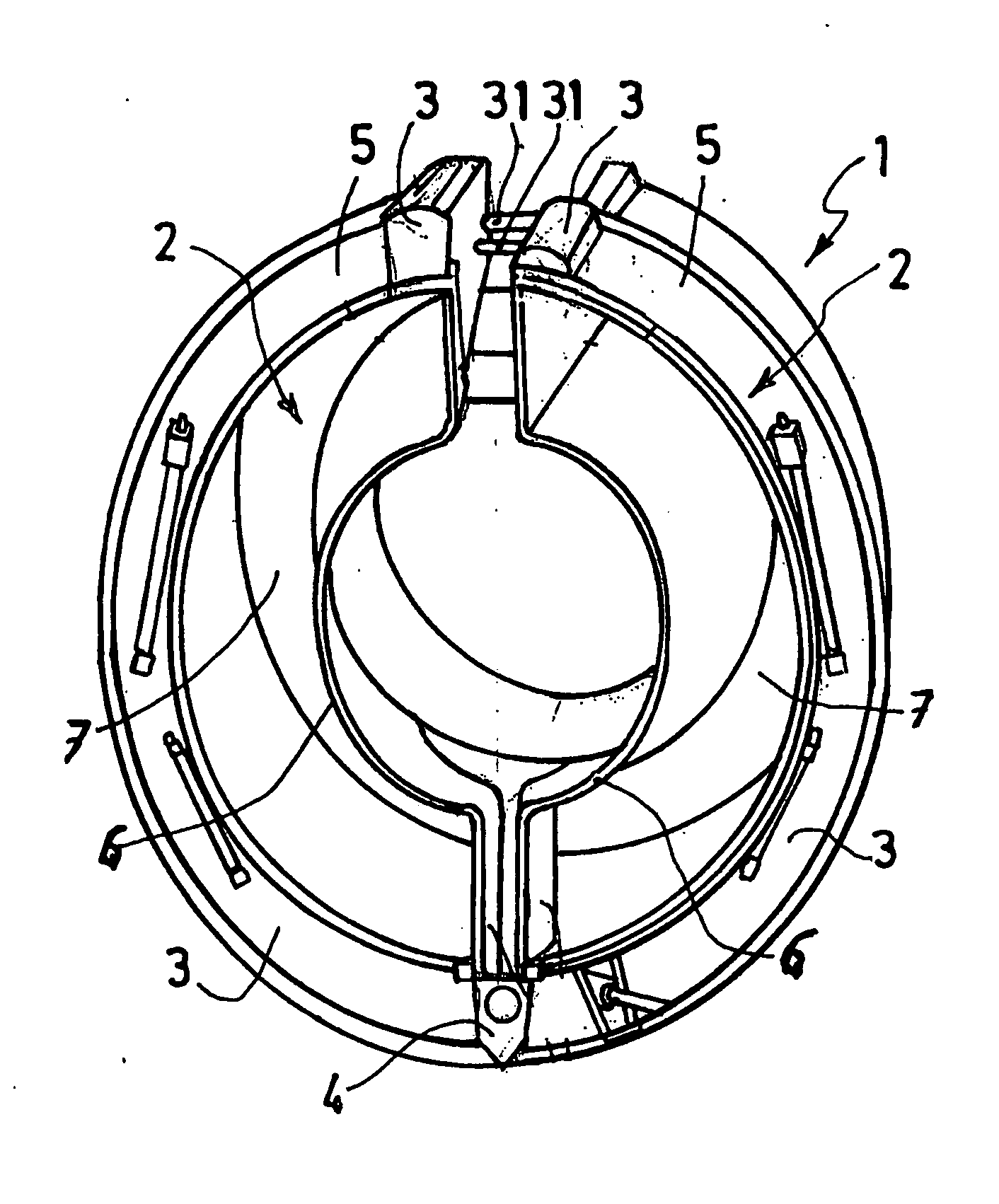
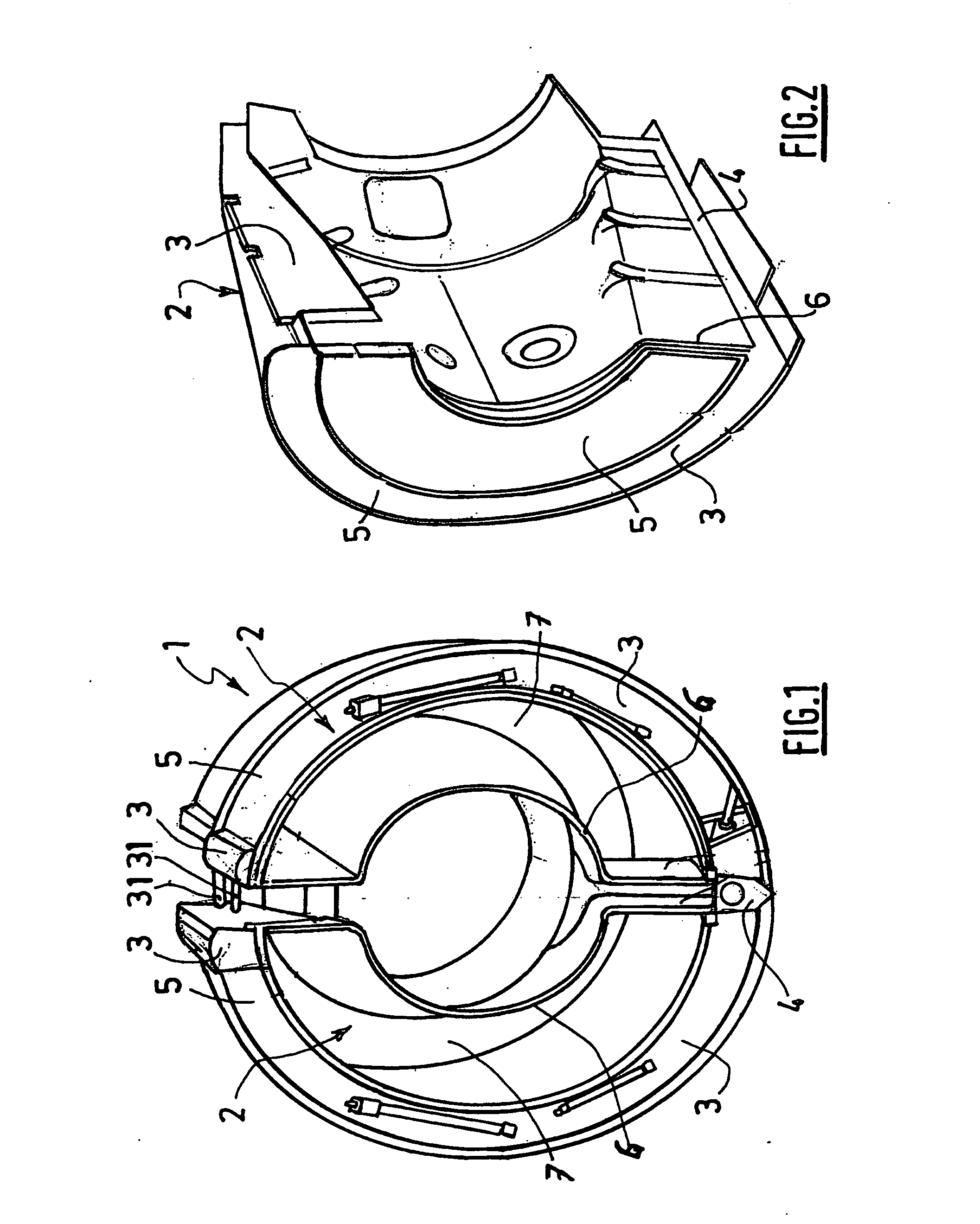
[0032]FIG. 1 shows a rear section 1 intended to equip a turbofan jet engine nacelle.

[0033]The rear section 1 is produced in the form of two substantially hemicylindrical half-portions 2 intended to be fastened around the jet engine on either side of a strut (not shown).

[0034]Each half-portion 2 comprises an upper longitudinal beam 3 and a lower longitudinal beam 4 serving together as a reinforcement for an external structure 5 intended to provide the outer aerodynamic continuity of the nacelle and an internal structure 6 intended to surround a rear portion of the jet engine. The external structure 5 and the internal structure 6 together define a flow duct 7 for the cold stream.

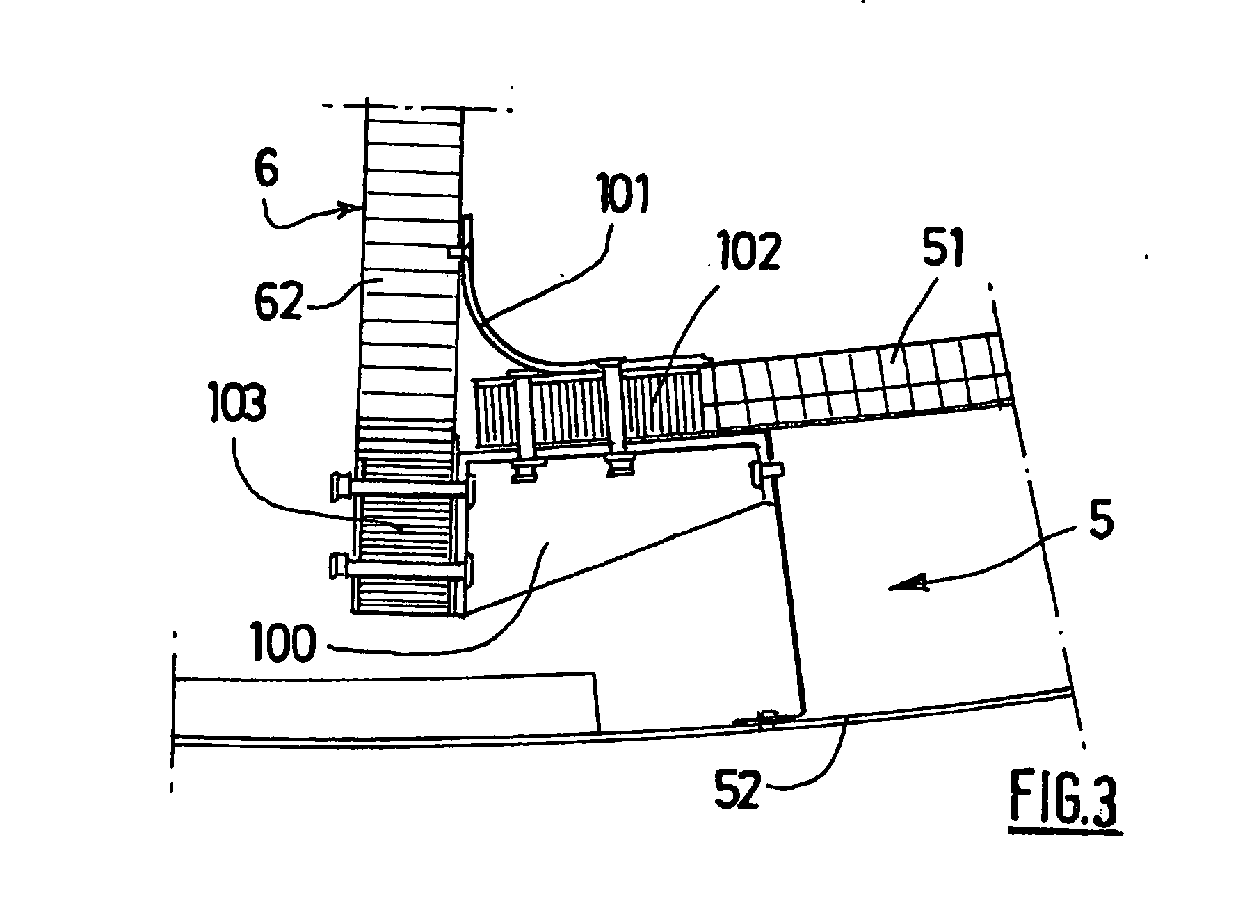
[0035]More precisely, the flow duct 7 is delimited by the internal structure 6, on the one hand, and by an inner wall 51 of the external structure 5. The external structure 5 also has an external wall 52 intended for its part to provide the external aerodynamic continuity.

[0036]The internal wall 51 and the ext...


PUM


Abstract

The present invention relates to a turbofan jet engine nacelle intended to be attached to a structure of an aircraft by an engine strut and comprising a forward air inlet section, a mid-section intended to surround a jet engine fan, and an aft section having an internal structure intended to serve as a casing for an aft portion of the jet engine and, together with an external structure (5), defining a flow duct (7) for a secondary stream, the internal structure having substantially radial extensions (61) passing through the duct and via which it is connected to an inner panel (51) of the external structure by means of at least one corresponding stiffener (110) having a right-angled general shape, characterized in that the stiffener is also fastened in an external panel (52) of the external structure.

Description

TECHNICAL FIELD[0001]The present invention relates to a jet engine nacelle intended to be attached to a structure of an aircraft by a connection strut.BACKGROUND[0002]An aircraft is propelled by a number of jet engines each housed in a nacelle.[0003]A nacelle generally has a tubular structure comprising an air inlet upstream of the jet engine, a mid-section intended to surround a fan of the jet engine, and a downstream section optionally incorporating thrust reversal means and intended to surround the combustion chamber of the jet engine, and is generally terminated by an exhaust nozzle whose outlet is situated downstream of the jet engine.[0004]Modern nacelles are intended to accommodate a turbofan jet engine designed to generate, on the one hand, a hot air stream (also known as the primary stream) from the combustion chamber of the jet engine, and, on the other hand, a cold air stream (secondary stream) from the fan and flowing outside the turbofan through an annular passage, also...

Claims


Application Information

Patent Timeline
IPC IPC(8): F02K3/04
CPCB64D29/08
Inventor BOUILLON, FLORENTDUNLEAVY, PAT
Owner AIRCELLE
Features
  • Generate Ideas
  • Intellectual Property
  • Life Sciences
  • Materials
  • Tech Scout
  • Unparalleled Data Quality
  • Higher Quality Content
  • 60% Fewer Hallucinations
Learn More