Dynamic allocation of drive torque

Active Publication Date: 2015-03-05
FORD GLOBAL TECH LLC
View PDF2 Cites 14 Cited by
  • Summary
  • Abstract
  • Description
  • Claims
  • Application Information

AI Technical Summary

Benefits of technology

[0005]In one example, the above issue may be at least partly addressed by a method for a hybrid electric vehicle comprising: dynamically limiting a maximum available torque for an engine based on each of an operator selected vehicle performance mode and a change in torque demand, the maximum available torque limited between a first torque limit based on performance and a second torque limit based on fuel economy; and providing motor torque to the vehicle based on the dynamic limiting. In this way, a better balance can be struck between engine performance and fuel economy.
[0006]For example, in response to an operator pressing an “ECO” button of a vehicle, a fuel economy mode of vehicle operation may be selected. Accordingly, the settings of various engine operating parameters may be adjusted so as to improve fuel economy while minimizing reduction in performance when fuel economy is the priority. In particular, a maximum available engine torque may be limited. The constrained maximum available engine torque may be learned (e.g., learned up or learned down) during engine operation, at different engine speed ranges, based on a spark retard torque ratio (that is, a ratio of maximum engine torque at borderline

Problems solved by technology

Specifically, when there is insufficient vacuum for purging a fuel canister, the maximum engine torque is limited to a level that provides the required purge vacuum.
However the inventors herein have identified a potential issue with such an approach.
The adjusting of maximum engine torque to meet vacuum demand can result in too much limiting of the maximum torque, which hurts fuel economy.
As such, it may be difficult to trade-off best fuel economy and maximum engine performance.
The setting for best performance will have a maximum engine torque in the borderline spark reduction region, which is i

Method used


Image

  • Dynamic allocation of drive torque
  • Dynamic allocation of drive torque
  • Dynamic allocation of drive torque

Examples


Example

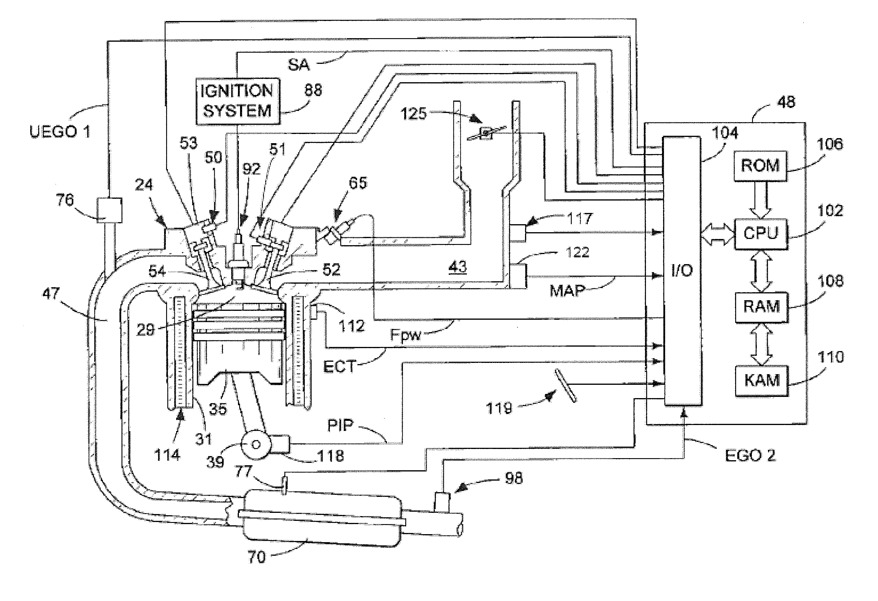
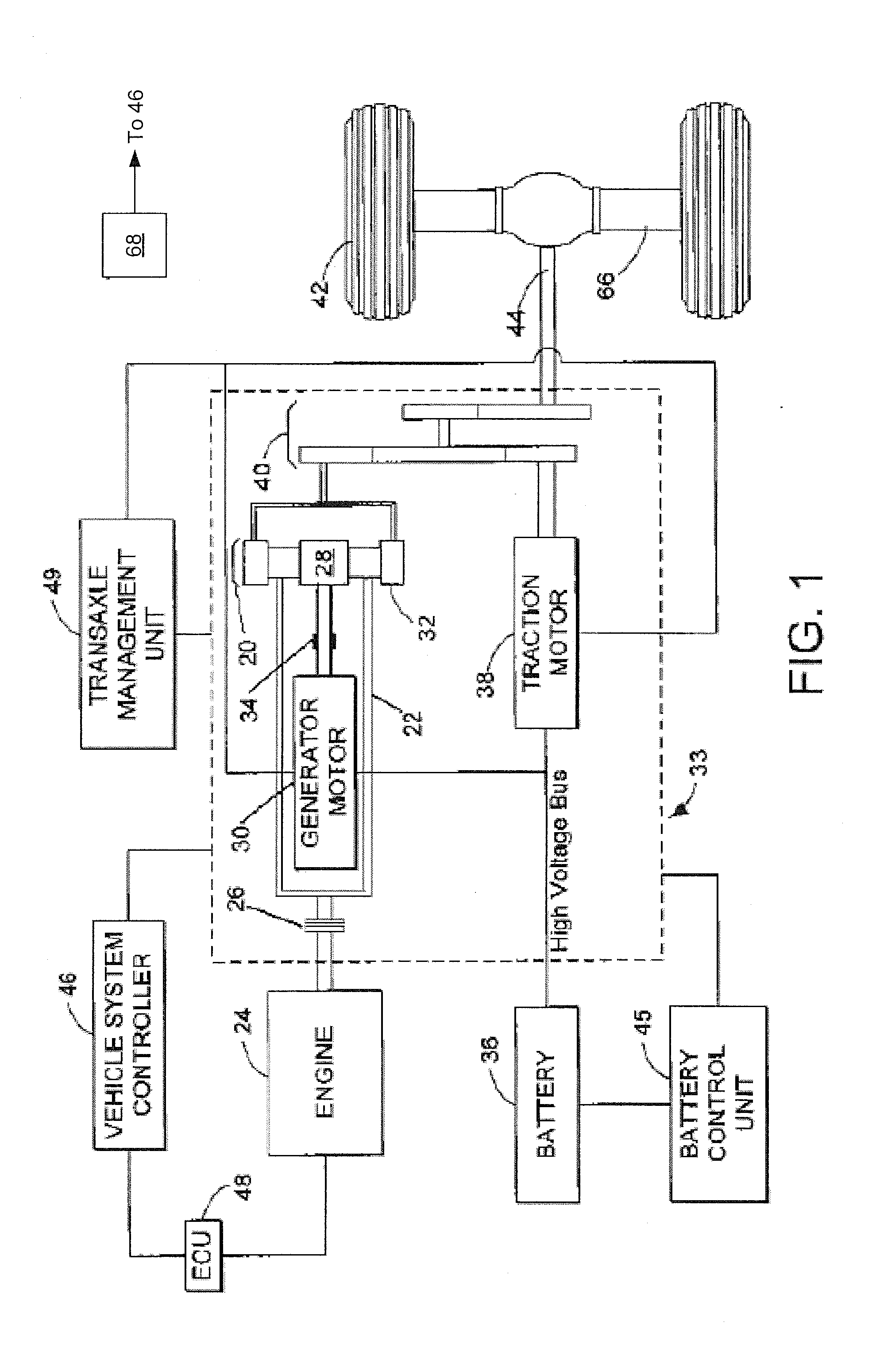
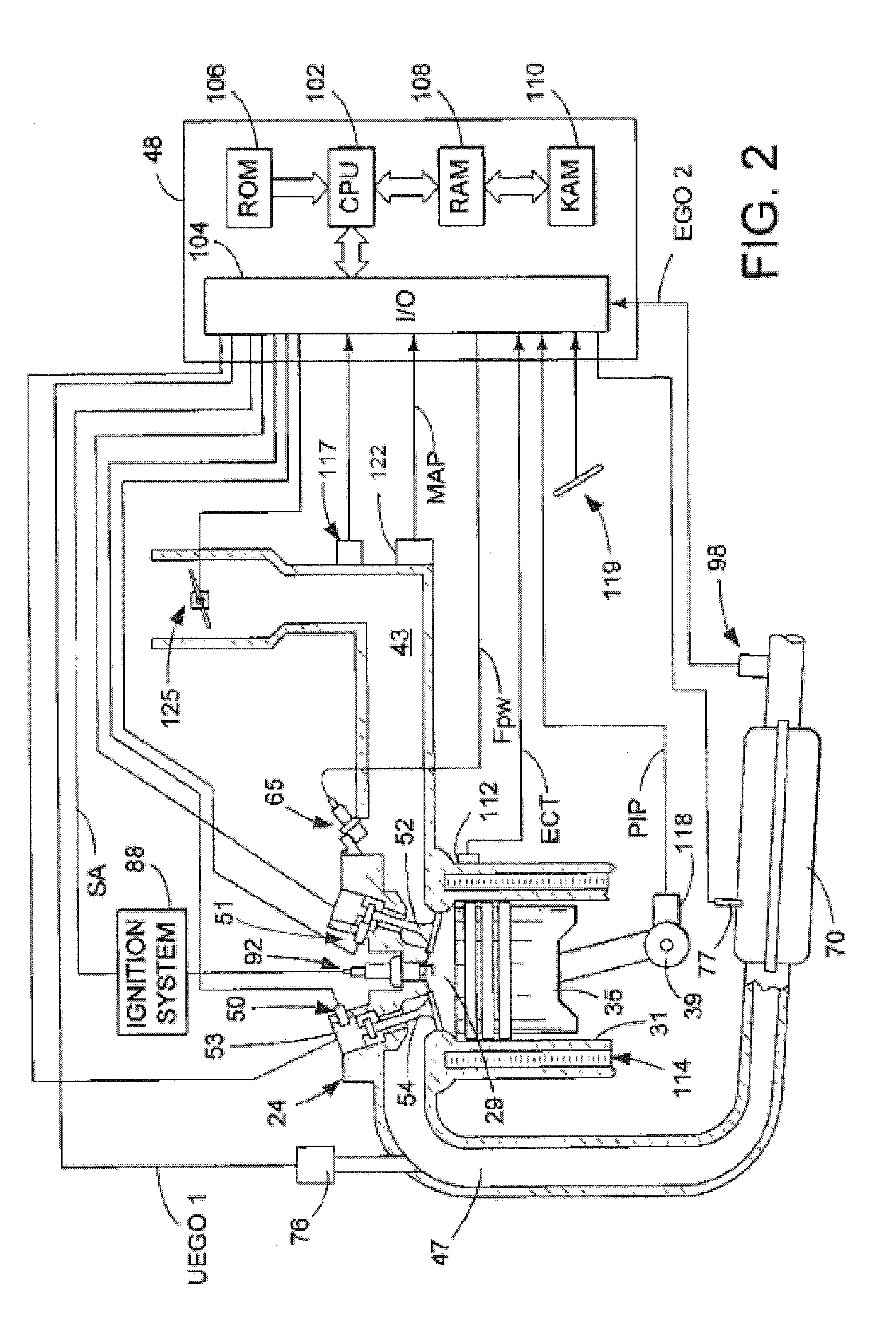
[0016]Methods and systems are provided for dynamically adjusting a maximum engine torque available in a hybrid electric vehicle, such as the vehicle system of FIGS. 1-2. Based on whether an operator has selected a performance mode or an economy mode of vehicle operation, and further based on steady-state or transient conditions (FIG. 5), a limiting of the maximum engine torque may be varied. A controller may be configured to perform a control routine, such as the routine of FIG. 3 to apply a more constrained maximum torque more when operating in an economy mode or in the presence of steady-state conditions when operating in a performance mode to achieve higher fuel economy. In comparison, the controller may apply a less constrained maximum torque in the presence of transients when operating in the performance mode to achieve improved vehicle acceleration. The controller may also perform a routine, such as the example routine of FIG. 4, to learn the value of the more constrained maxi...


PUM


Abstract

Methods and systems are provided for dynamically allocating engine torque and motor torque in a hybrid vehicle to meet operator torque demand. The allocation is adjusted by constraining the maximum engine torque allowable under selected conditions to provide a better trade-off between performance and fuel economy. A maximum engine torque that provides best fuel economy is learned during engine operation at different engine speed-load conditions based on a deviation in spark retard torque ratio from a threshold ratio as spark timing is moved to MBT.

Description

TECHNICAL FIELD[0001]The present application relates generally to dynamic allocation of maximum engine torque in a hybrid electric vehicle to improve fuel economy.BACKGROUND AND SUMMARY[0002]In some vehicles, such as hybrid vehicles, a high level system controller may control a plurality of power and / or torque sources for propelling the vehicle. For example, the controller may allocate a total drive request among the various sources in different ways depending on operating conditions. During the allocation, a vehicle controller may consider one or more factors such as the available output range of the individual torque sources. For example, an engine may have a variable maximum torque output depending on operating conditions, and it may further change as the engine ages, etc.[0003]One example approach for dynamic torque allocation is shown by Martin et al. in U.S. Pat. No. 7,967,720. Therein, the maximum torque allowed for the engine is adjusted during vehicle operation based on vac...

Claims


Application Information

Patent Timeline
IPC IPC(8): B60W20/00
CPCY10S903/902B60W20/108B60W10/06B60W10/08B60W20/20B60W40/00B60W2710/0666B60W2710/083B60W2540/215B60K6/445B60W50/082B60W50/085B60W30/1882B60W2050/0088B60W2540/10B60W2540/106B60W20/10Y02T10/84B60W20/16Y02T10/40Y02T10/62B60W20/15
Inventor MARTIN, DOUGLAS RAYMONDHALADYNA, TEDMILLER, KENNETH JAMES
Owner FORD GLOBAL TECH LLC
Why Eureka
Try Eureka