High-speed pantograph head

A pantograph, high-speed technology, applied in the field of pantograph heads, can solve problems such as unfavorable dynamic current receiving, and achieve the effects of improving followability, reducing air resistance and enhancing stability

Inactive Publication Date: 2011-06-08
CENT SOUTH UNIV
View PDF6 Cites 14 Cited by
  • Summary
  • Abstract
  • Description
  • Claims
  • Application Information

AI Technical Summary

Problems solved by technology

Not conducive to dynamic flow under high-speed conditions

Method used


Image

  • High-speed pantograph head
  • High-speed pantograph head
  • High-speed pantograph head

Examples


Embodiment 1

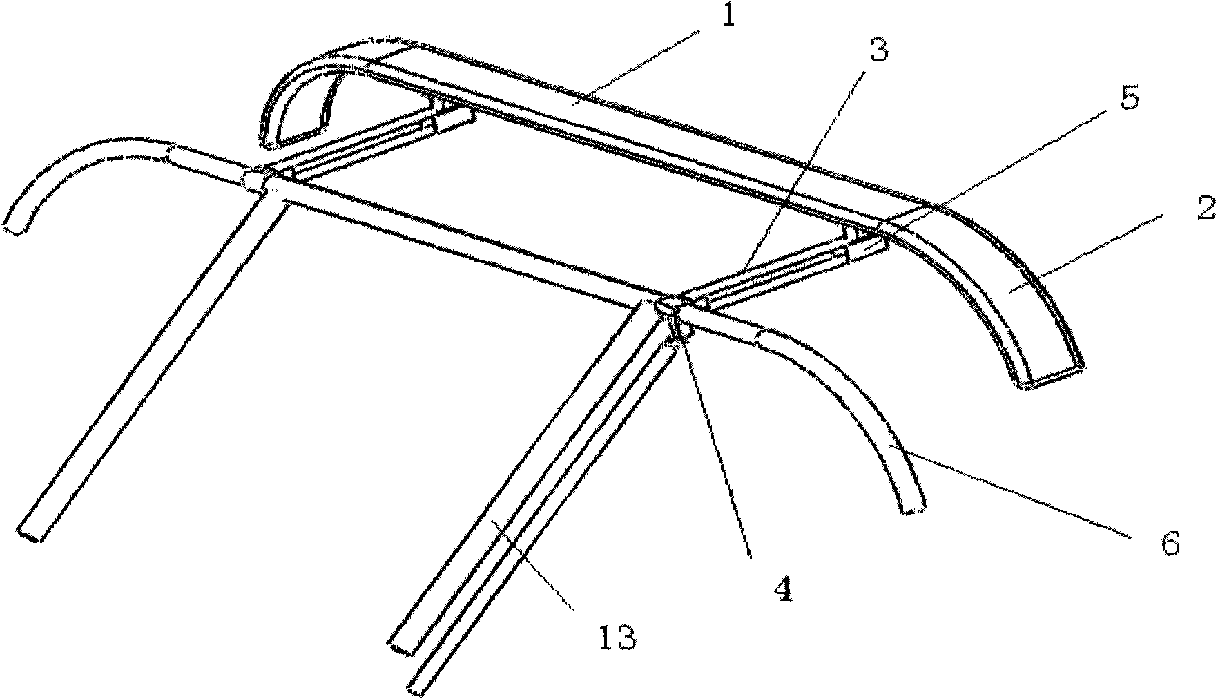
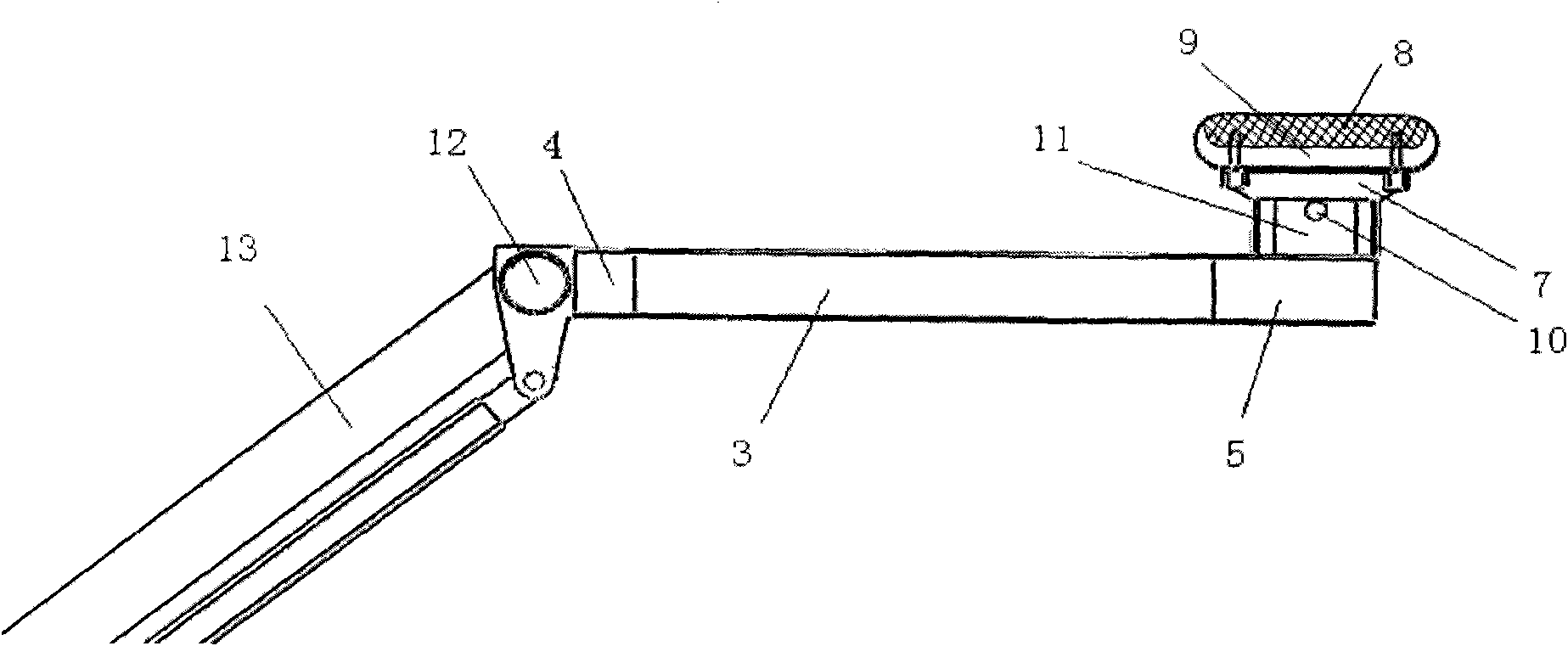
[0024] figure 1 and figure 2 Shown, the shape of the section of slide plate 1 is streamlined, and the bottom of slide plate 1 is a strip-shaped slide plate groove 9, and slide plate groove 9 is embedded with a carbon slide block 8 or powder metallurgy slide block, also can be other materials (such as powder metallurgy material), the slide plate groove 9 is connected to the bracket 7 by screws, the bracket 7 is connected to the support 11 on the front end 5 of the frame spring 3 by a pin 10, and the front end 5 of the frame spring 3 is fixedly connected to the support 11 , the rear end 4 of the frame spring 3 is fixedly connected to the hinge 12 of the double-rod upper frame 13 of the pantograph, the two ends of the slide plate 1 are provided with small bow horns 2, and the first big bow horn 6 is inserted and fixed on two In the hinge 12 of the frame 13 on the rod. The streamline shape of the cross section of the skateboard 1 is that the upper and lower sides are straight l...

Embodiment 2

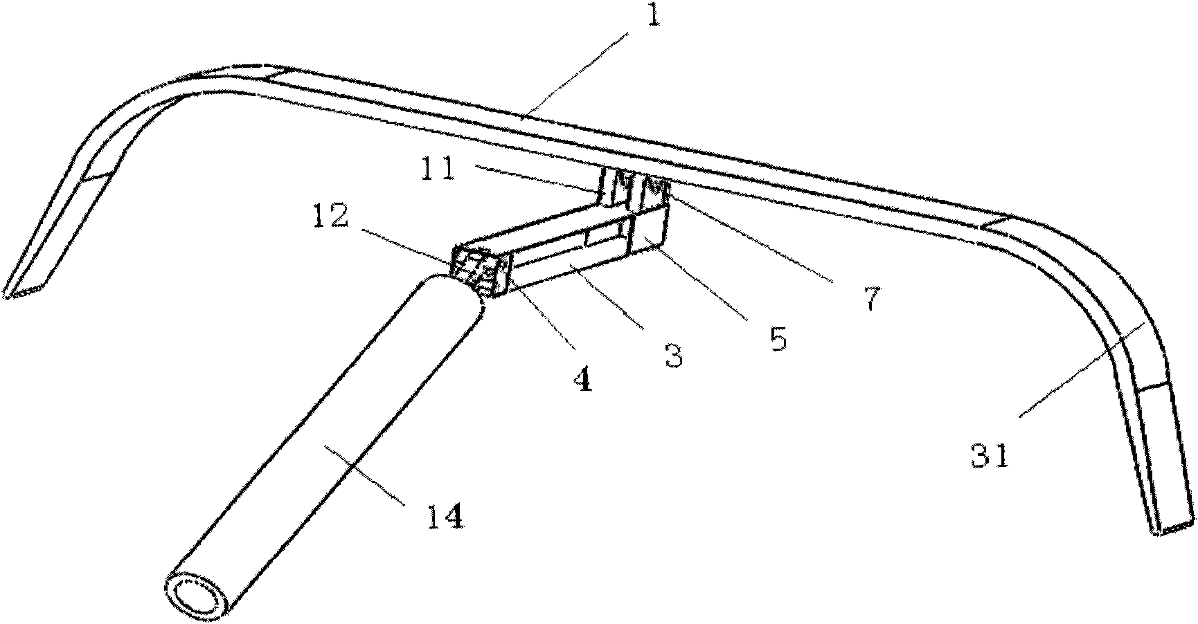
[0026] image 3 Shown, the shape of the section of slide plate 1 is streamlined, and the bottom of slide plate 1 is a strip-shaped slide plate groove 9, and slide plate groove 9 is embedded with a carbon slide block 8 or powder metallurgy slide block, also can be other materials (such as powder metallurgy material), the slide plate groove 9 is connected to the bracket 7 with screws, the center of the lower part of the bracket 7 is connected to the support 11 on the front end 5 of the frame spring 3 with a pin 10, and the front end 5 of the frame spring 3 is connected to the support 11 Fixed connection, the rear end 4 of the frame spring 3 is fixed on the hinge 12 of the single-rod upper frame 14 of the pantograph, and the two ends of the slide plate 1 are provided with a second large bow angle 31 . The streamline shape of the cross section of the skateboard 1 is that the upper and lower sides are straight lines, and the left and right ends are elliptical or circular.

[0027]...


PUM


Abstract

The invention discloses a high-speed pantograph head, comprising a sliding plate, small bow angles, large bow angles and a frame-shaped spring, wherein the section of the sliding plate is in a stream line form, the lower part of the sliding plate is an elongated sliding plate slot, the slot is embedded with carbon slide blocks or other materials, the frame-shaped spring is connected below the sliding plate by virtue of a bracket, the front end of the frame-shaped spring is connected with the sliding plate by virtue of a support and the bracket, the rear end of the frame-shaped spring is hinged with the upper frame of a pantograph, and a group of large bow angles are inserted and fixed in a hinge at the upper end of the upper frame of the pantograph. Under the coordination of a pantograph balanced beam, the frame-shaped spring can always maintain the sliding plate of the pantograph to be parallel to a guide rail plane, and the sliding plate can be always in close contact with a contact wire under the regulating action of the bracket. The structure of the pantograph head is simple, the weight is light, the air resistance when the pantograph head moves, the impact resistance is high, the current of the pantograph at a high speed is favourable, the current of the pantograph of a train on a conventional railway or a light railway can be improved.

Description

technical field [0001] The invention relates to a pantograph bow head, in particular to a high-speed pantograph bow head. Background technique [0002] On vehicles such as electric locomotives, EMUs or electric operating vehicles in electrified railways and urban rail transit, pantographs are required to take current from the catenary. The electrified railway adopts electric traction. When the train is in motion, it uses the pantograph to obtain electric energy from the catenary. In order to ensure the smooth and safe operation of the train, it is necessary to ensure that the power supply is absolutely reliable and uninterrupted, that is, the current receiving state of the pantograph is good. Otherwise it will affect the operation of the train and the performance of the electric drive system. In the high-speed running state, the requirements for the pantograph are higher. [0003] In order to ensure good current receiving characteristics of the pantograph-catenary, the str...

Claims


Application Information

Patent Timeline
Patent Type & Authority Applications(China)
IPC IPC(8): B60L5/20
Inventor 李丰良
Owner CENT SOUTH UNIV
Why Eureka
Try Eureka