Electronic device and filter

a technology of electronic devices and filters, applied in waveguides, antenna details, antennas, etc., can solve the problems of affecting the quality of the balanced output, so as to facilitate the adjustment of balance characteristics, facilitate miniaturization, and achieve superior balance characteristics

Active Publication Date: 2009-07-14
TDK CORPARATION
View PDF19 Cites 15 Cited by
  • Summary
  • Abstract
  • Description
  • Claims
  • Application Information

AI Technical Summary

Benefits of technology

[0011]The present invention has an object thereof to solve the above-mentioned problems by providing an electronic device and a filter that are easy to miniaturize and capable of transmitting a balanced signal with superior balance characteristics.
[0049]The filters of the present invention facilitate miniaturization and enable the balanced signal to be transmitted with superior balance characteristics, by virtue of the arrangement such that a pair of balanced terminals is connected to a pair of interdigital-coupled quarter-wave resonators, respectively, and another resonator and the pair of quarter-wave resonators are electromagnetic-coupled at the second resonance frequency of a low frequency.

Problems solved by technology

Nevertheless, in the laminate type balun transformers described in the above-mentioned Publications No. 2002-190413 and No. 2003-007537, the entire dimension is limited by the dimension of the half-wave resonator (the dimension of the half-wave of the operating frequency), making it difficult to achieve miniaturization.
However, due to unnecessary coupling between the lines, and departure from an ideal state of physical arrangement balance, the amplitude balance and the phase balance at the time of balanced output may collapse, failing to obtain the desired characteristics.
Similarly, in the laminate type band pass filters described in the above-mentioned Publications No. 2005-045447 and No. 2005-080248, the half-wave resonator is basically used, and hence the entire dimension is limited by the dimension of the half-wave resonator, making it difficult to achieve miniaturization.
Similarly, in the conventional antennas with the construction using the open-ended half-wave resonator, the whole device cannot be minimized because the dimension of the antenna depends on the half-wave of an operating frequency.
However, the use of the balun makes it impossible to miniaturize the whole device.
This is insufficient in terms of miniaturization.

Method used


Image

  • Electronic device and filter
  • Electronic device and filter
  • Electronic device and filter

Examples


first preferred embodiment

[0087]An electronic device according to a first preferred embodiment of the present invention will now be described.

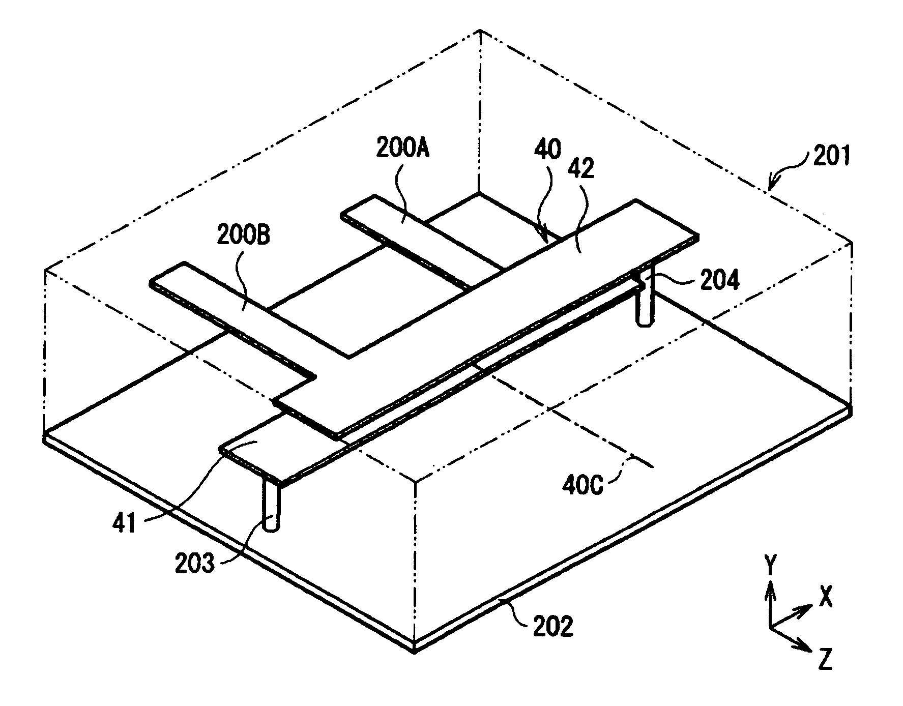
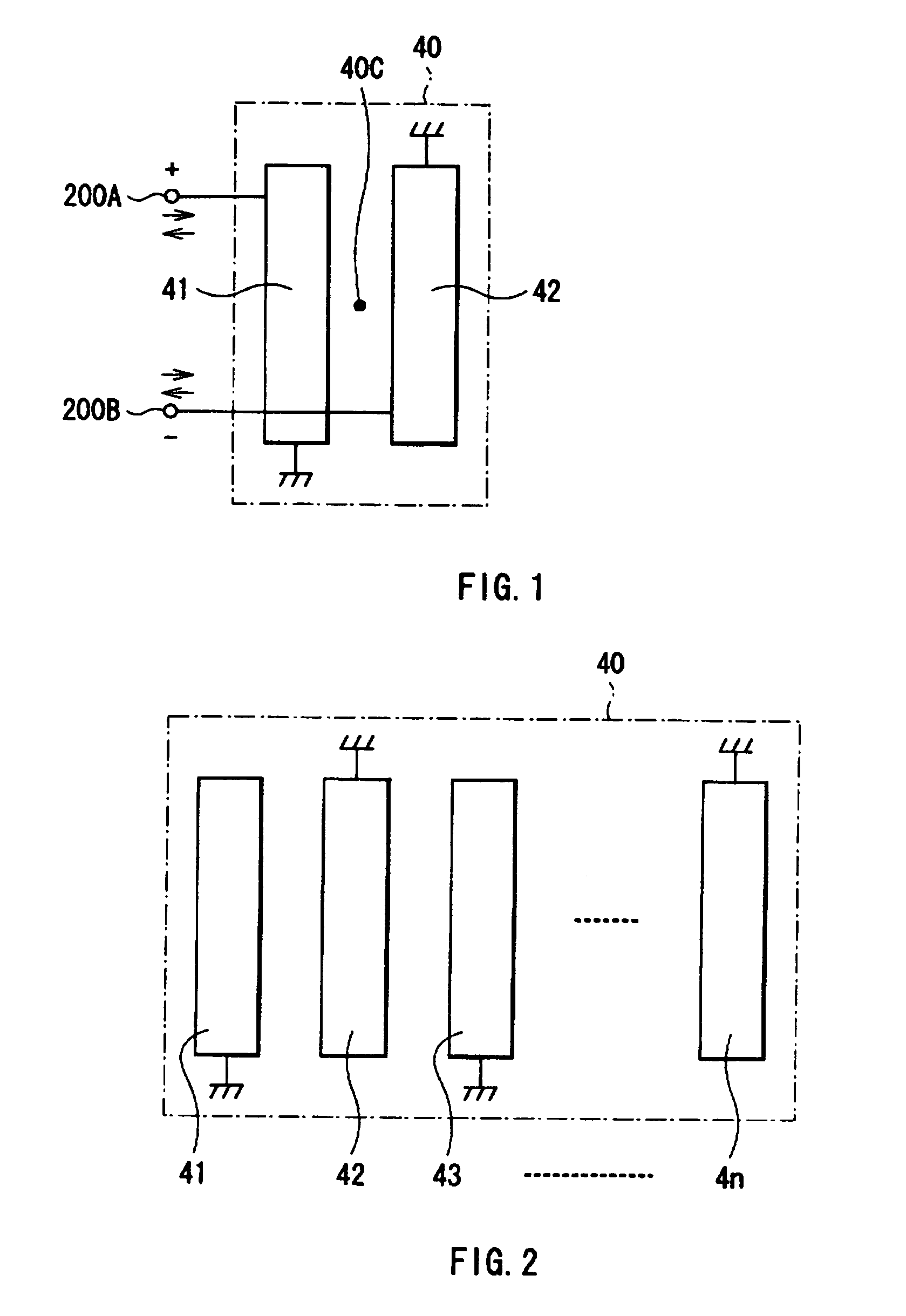
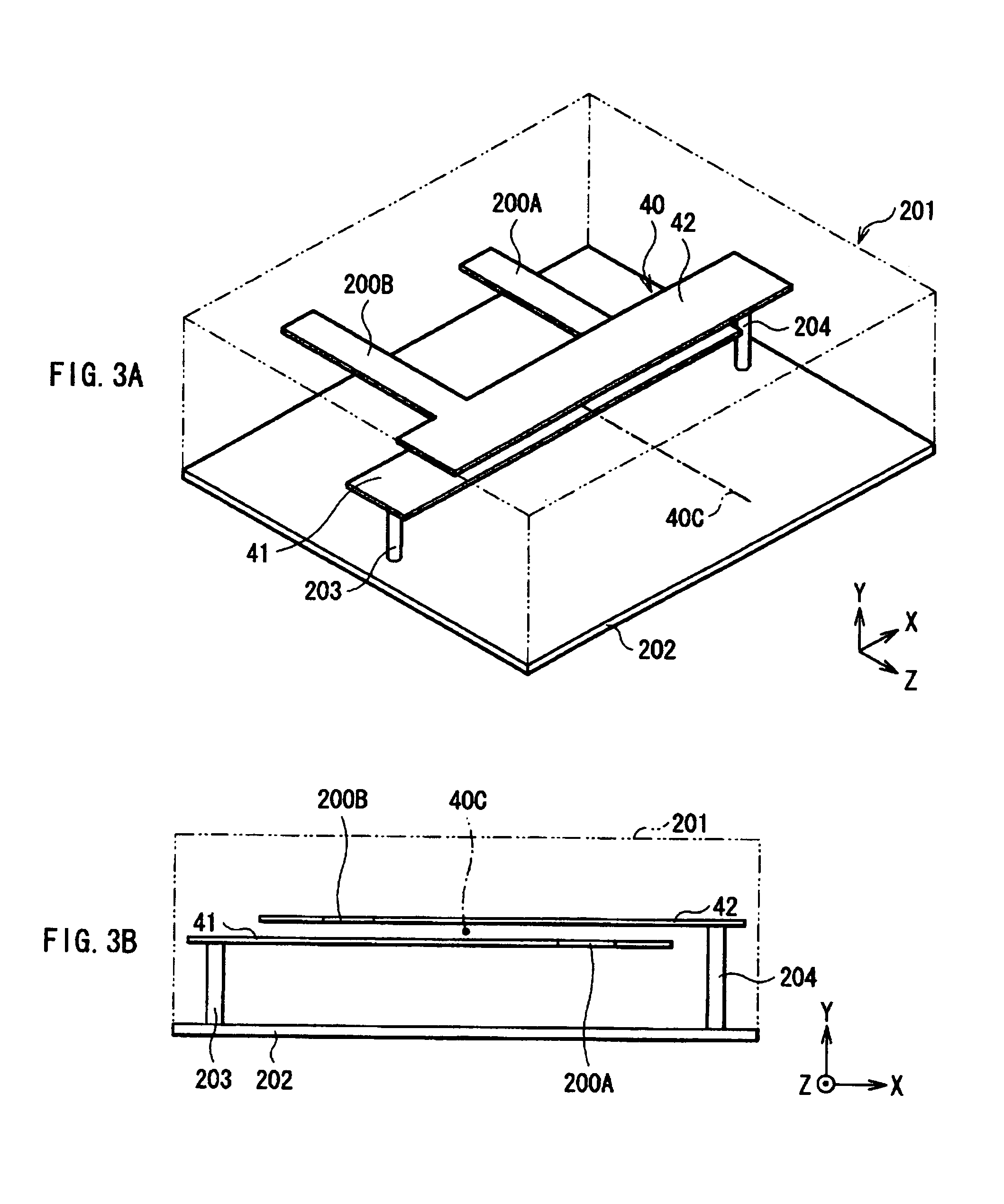
[0088]FIG. 1 shows a basic construction of the electronic device of the first preferred embodiment. This electronic device has a resonator 40 and a pair of balanced terminals 200A and 200B connected to the resonator 40. These components are constructed of a TEM line. For example, the TEM line can be constructed of a conductor pattern such as a strip line or a through conductor formed in the inside of a dielectric substrate. The term “TEM line” means a transmission line for transmitting an electromagnetic wave (a TEM wave) in which both of an electric field and a magnetic field exist only within a cross section perpendicular to a direction of travel of the electromagnetic wave.

[0089]The resonator 40 is constructed of a pair of interdigital-coupled quarter-wave resonators 41 and 42. One the balanced terminal 200A is connected to one of the quarter-wave resonators 41 and ...

second preferred embodiment

[0120]An electronic device according to a second preferred embodiment of the present invention will be described below. The second preferred embodiment is directed to a construction of a filter as an electronic device. That is, at least either an input end or an output end is provided with a balanced terminal, and a resonator on a side having at least the balanced terminal is constructed of at least a pair of interdigital-coupled quarter-wave resonators, as in the foregoing first preferred embodiment. As a filter having a balanced terminal, there are three types of: unbalanced input / balanced output type; balanced input / unbalanced output type; and balanced input / balanced output type.

[0121]FIG. 11A illustrates a first basic construction when the filter of the second preferred embodiment is applied to the unbalanced input / balanced output type. The filter of unbalanced input / balanced output type has a resonator 1 for input disposed on an input end side, a resonator 2 for output disposed...

first specific

Constructional Example

[0149]FIGS. 15A and 15B illustrate a first specific constructional example of the filter according to the second preferred embodiment. FIG. 15B illustrates a state when viewed from a side surface direction of an output end side. This filter has a dielectric substrate 61 formed of a dielectric material. The dielectric substrate 61 is of a multilayer structure and has its inside a conductive line pattern (a strip line). A resonator 1 that is constructed of a pair of quarter-wave resonators 11 and 12, and a resonator 2 that is constructed of a pair of quarter-wave resonators 21 and 22, and an unbalanced input terminal 3, and a pair of balanced output terminals 4A and 4B are constructed of the internal line pattern. To obtain this structure, for example, a laminate structure may be formed by the step of preparing a plurality of sheet-shaped dielectric substrates; the step of forming the respective resonators and the respective terminal parts on the sheet-shaped die...


PUM


Abstract

A pair of balanced terminals is connected to a pair of interdigital-coupled quarter-wave resonators in an electronic device. This electronic device has a first resonance mode that resonates at a first resonance frequency f1 higher than a resonance frequency f0 in each of the pair of quarter-wave resonators when establishing no interdigital-coupling, and a second resonance mode that resonates at a second resonance frequency f2 lower than the resonance frequency f0. The second resonance frequency f2 of a low frequency is set as an operating frequency. This provides an electronic device and a filter that facilitate miniaturization and enable a balanced signal to be transmitted with superior balance characteristics.

Description

BACKGROUND OF THE INVENTION[0001]1. Field of the Invention[0002]The present invention relates to an electronic device and a filter that are provided with a balanced terminal.[0003]2. Description of the Related Art[0004]Examples of electronic devices having a balanced terminal are filters and antennas. As a filter having a balanced terminal, there is known for example a band pass filter of unbalanced input / balanced output type. As such a filter, there is one using a balun. The balun is used to perform mutual conversion between an unbalanced signal and a balanced signal. Radio communication equipments such as mobile or cellular phones demand reductions in the dimension and thickness as a filter.[0005]In a line for transmitting an unbalanced signal, a signal is transmitted by the potential of a signal line with respect to a ground potential. In a line for transmitting a balanced signal, a signal is transmitted by the potential difference between a pair of signal lines. A balanced signa...

Claims


Application Information

Patent Timeline
Patent Type & Authority Patents(United States)
IPC IPC(8): H01P1/205H01P5/10H01P7/08H01Q1/50
CPCH01P1/205H01P1/20345
Inventor FUKUNAGA, TATSUYA
Owner TDK CORPARATION
Why Eureka
Try Eureka