Automatic camera calibration using GPS and solar tracking

a technology of automatic camera calibration and solar tracking, which is applied in the field of automatic camera calibration using gps and solar tracking, and can solve the problems of inability to provide camera calibration, use of expensive cameras, sensors or other hardware, and use of camera systems in moderately priced vehicles

Inactive Publication Date: 2011-04-28
GM GLOBAL TECH OPERATIONS LLC
View PDF4 Cites 30 Cited by
  • Summary
  • Abstract
  • Description
  • Claims
  • Application Information

AI Technical Summary

Benefits of technology

The present invention is about a way to automatically calibrate the aiming of a camera on a vehicle. It uses a GPS receiver and solar almanacs to predict where the sun will be in relation to the vehicle. This information is compared to what the camera can see, and then calculations are made to find the best way to aim the camera. This helps the camera do its other functions better.

Problems solved by technology

The technical problem addressed in this patent is the need for a lower cost sun visor control system that takes advantage of commonly-available sensors and systems on a vehicle and uses them to determine the optimum position of the sun visor. Additionally, the patent discusses the need for a camera calibration process that automatically calibrates camera orientation parameters as the vehicle is being driven where the vehicle-camera system continually adapts itself over time.

Method used


Image

  • Automatic camera calibration using GPS and solar tracking
  • Automatic camera calibration using GPS and solar tracking
  • Automatic camera calibration using GPS and solar tracking

Examples


Embodiment Construction

[0018]The following discussion of the embodiments of the invention directed to a system and method for automatically calibrating the aiming direction of a camera on a vehicle is merely exemplary in nature, and is in no way intended to limit the invention or its applications or uses.

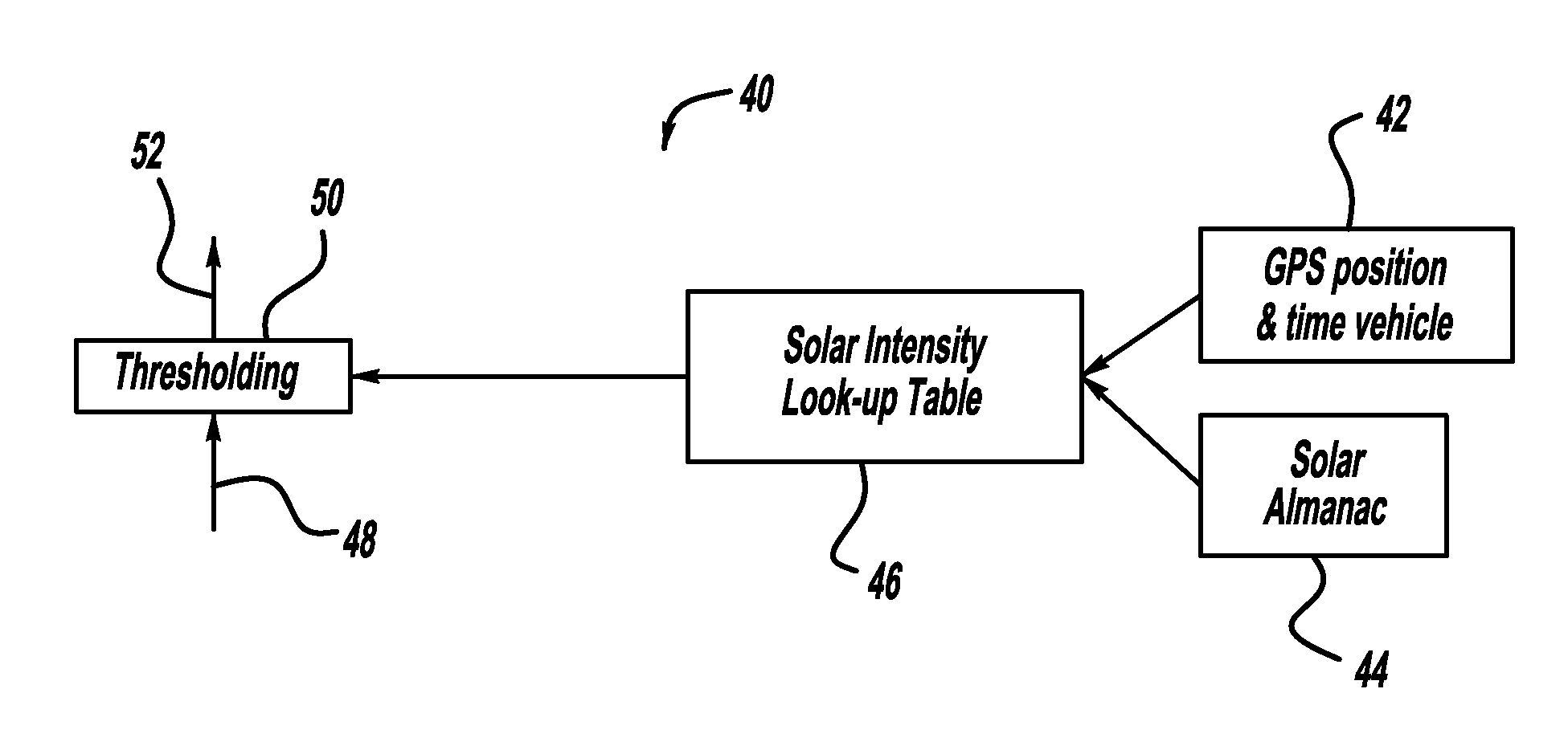
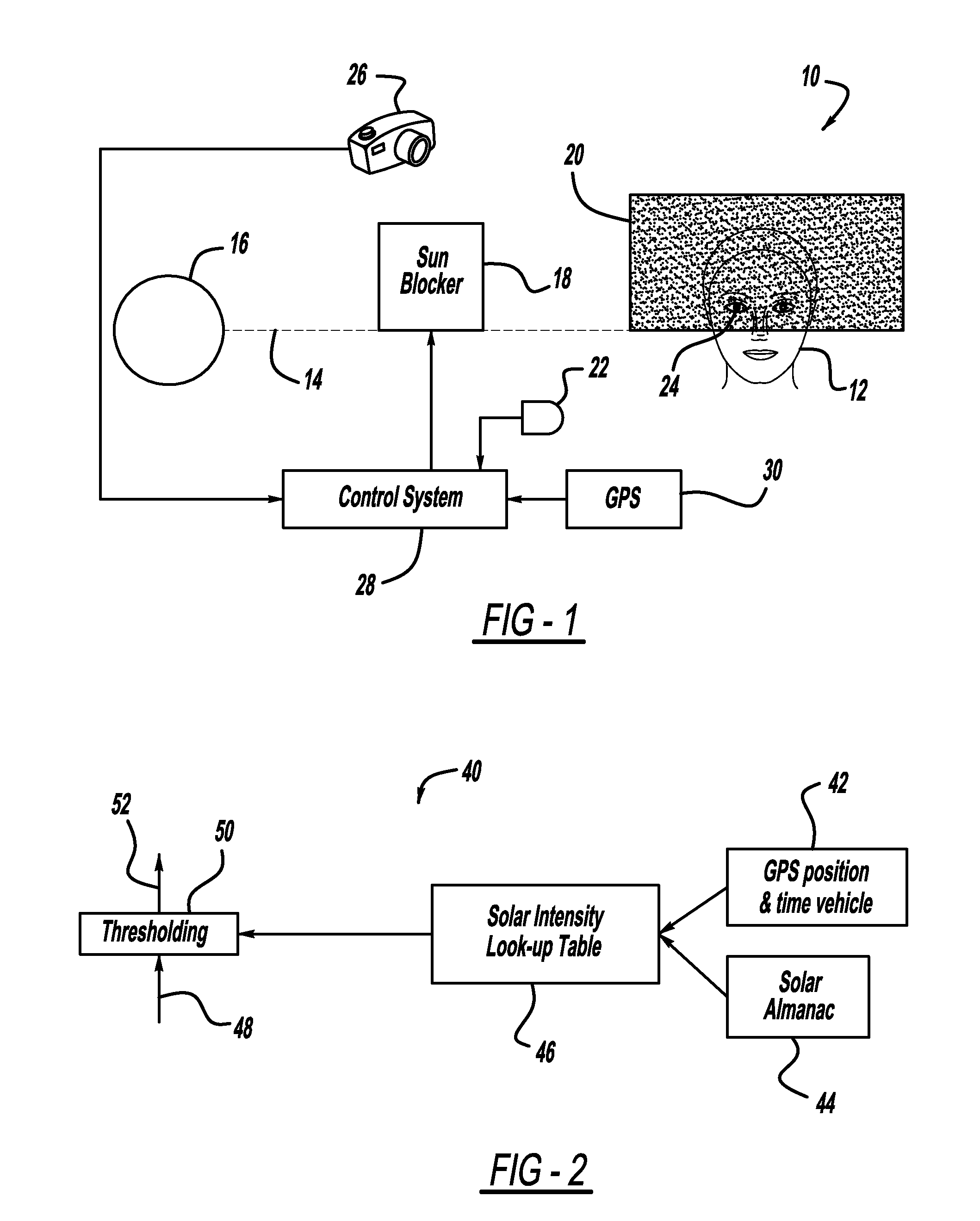
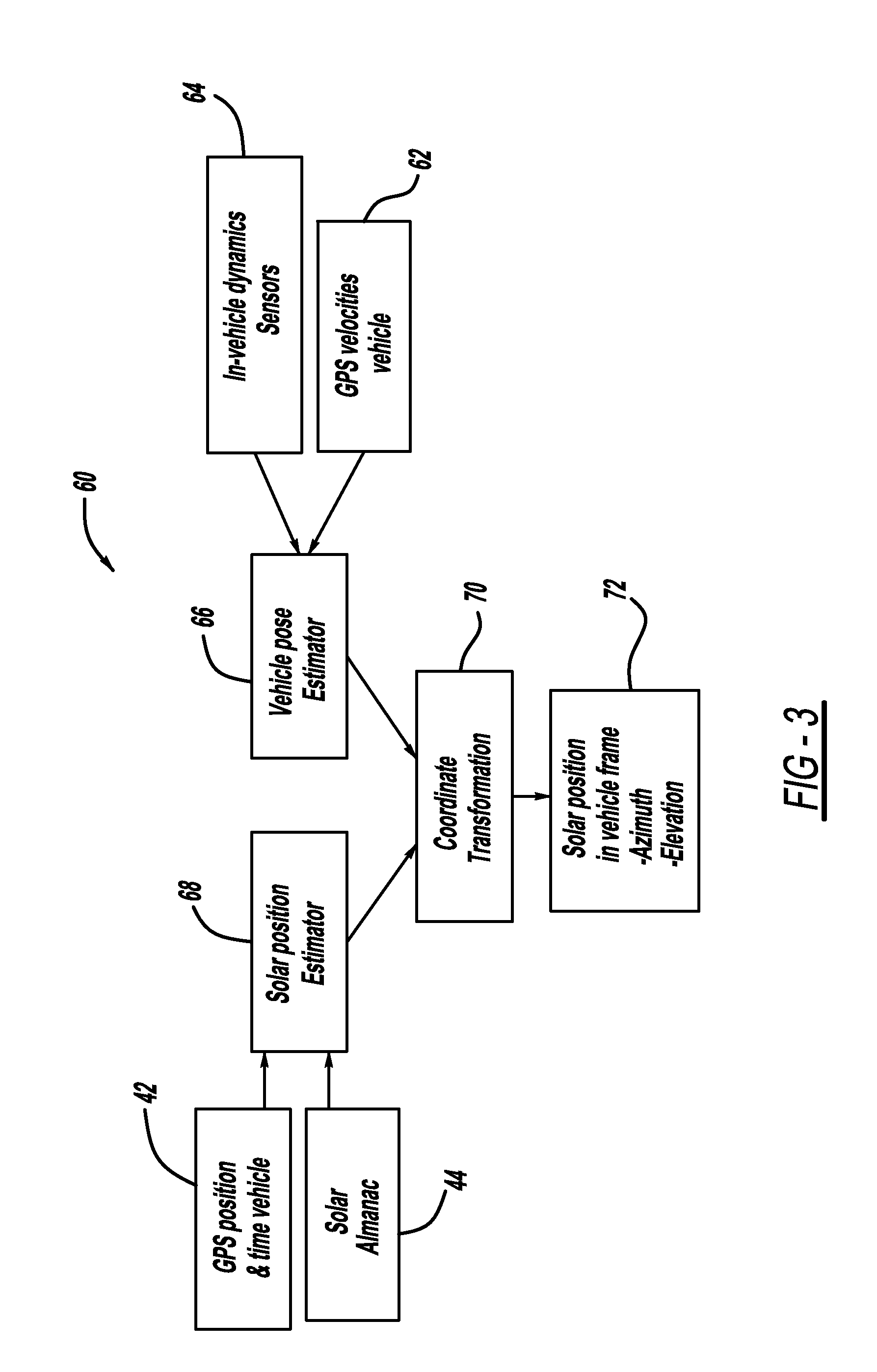
[0019]As mentioned above, automatic sun visor control systems known in the art and available on the market typically require dedicated cameras, sensors, or other hardware in order to operate, thus raising the cost of the system. The present invention proposes a system and method for controlling the position of an automatic sun visor in a vehicle, using commonly existing onboard systems and sensors to provide a low-cost yet robust sun visor controller. Specifically, the present invention uses Global Positioning System (GPS) data and vehicle dynamics sensors to determine the position of the sun relative to the vehicle, a forward-looking camera to fine-tune the GPS-based sun position data, a light intensity ...


PUM


Abstract

A system and method for automatically calibrating the aiming direction of a camera onboard a vehicle. The method uses GPS and solar almanac data to estimate the location of the sun relative to the vehicle, and compares this to the solar position in an image from the camera. The comparison is performed with an ongoing recursive calculation which yields an improved estimate of the sun position relative to the vehicle, while simultaneously calibrating the aiming direction of the camera. The aiming calibration data is used to improve the accuracy of the camera's images as used for all of the camera's other functions.

Description


Claims


Application Information

Patent Timeline
Owner GM GLOBAL TECH OPERATIONS LLC
Why Eureka
Try Eureka