

Image Pickup Apparatus
a technology of image pickup and lens barrel, which is applied in the direction of color television details, television system details, television systems, etc., can solve the problem of microphones being disposed inside the lens barrel
- Summary
- Abstract
- Description
- Claims
- Application Information
AI Technical Summary
Benefits of technology
Problems solved by technology
Method used
Image

Examples
first embodiment
[0015]An image pickup apparatus according to a first embodiment of the present invention will be described below with reference to the accompanying drawings.
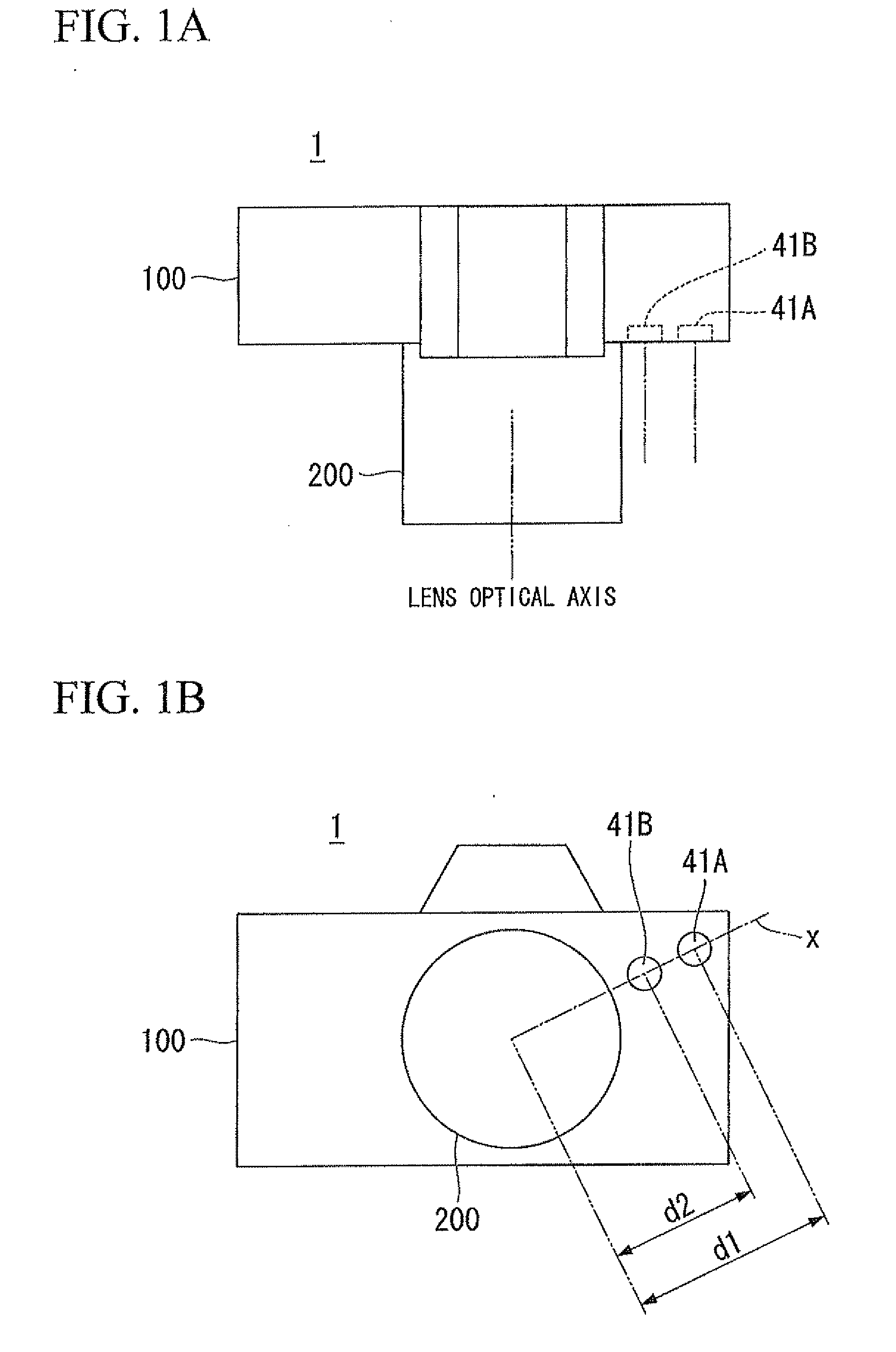
[0016]FIG. 1A is a top view of an image pickup apparatus 1 according to the first embodiment of the present invention. FIG. 1B is a front view of the image pickup apparatus 1.
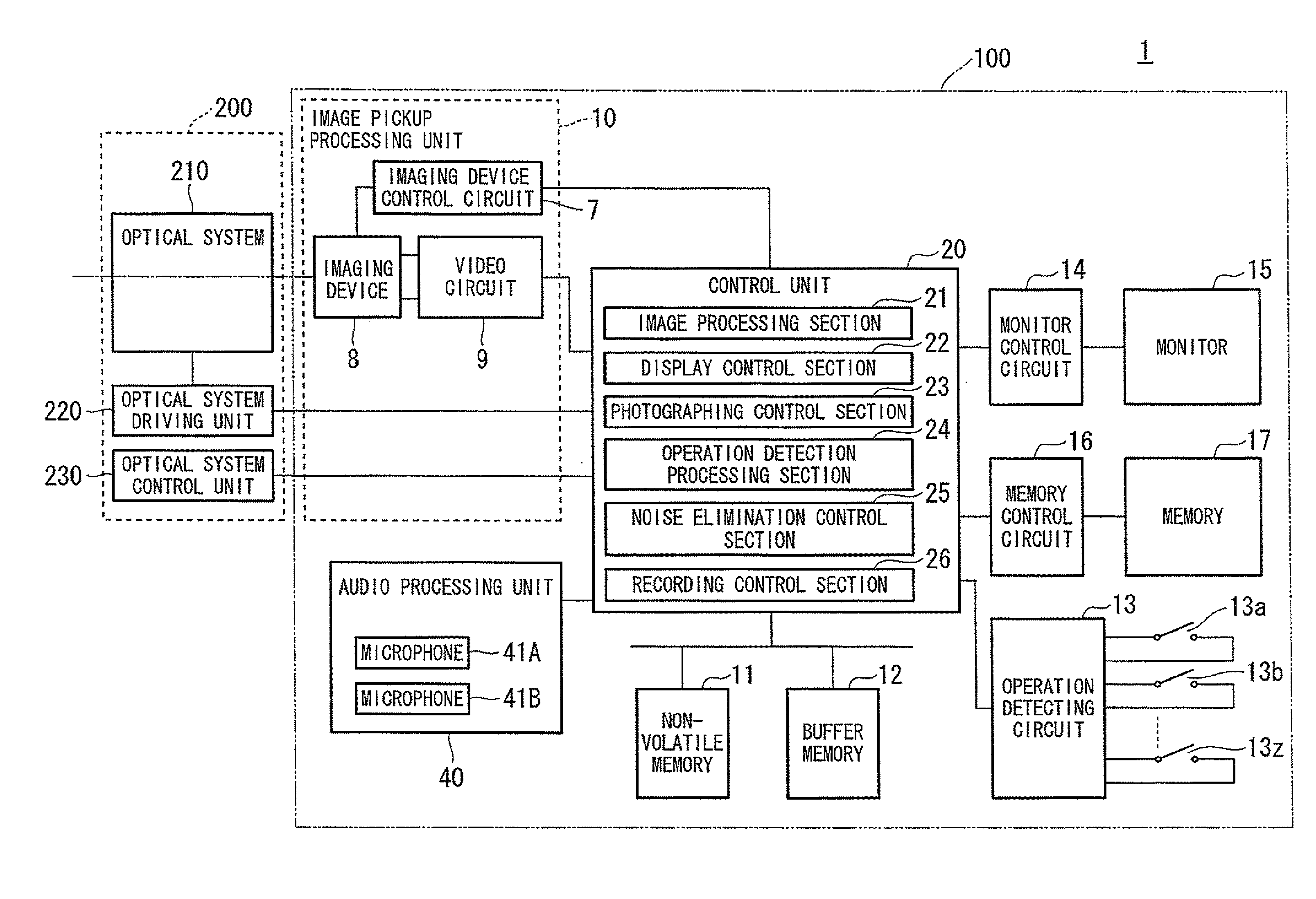
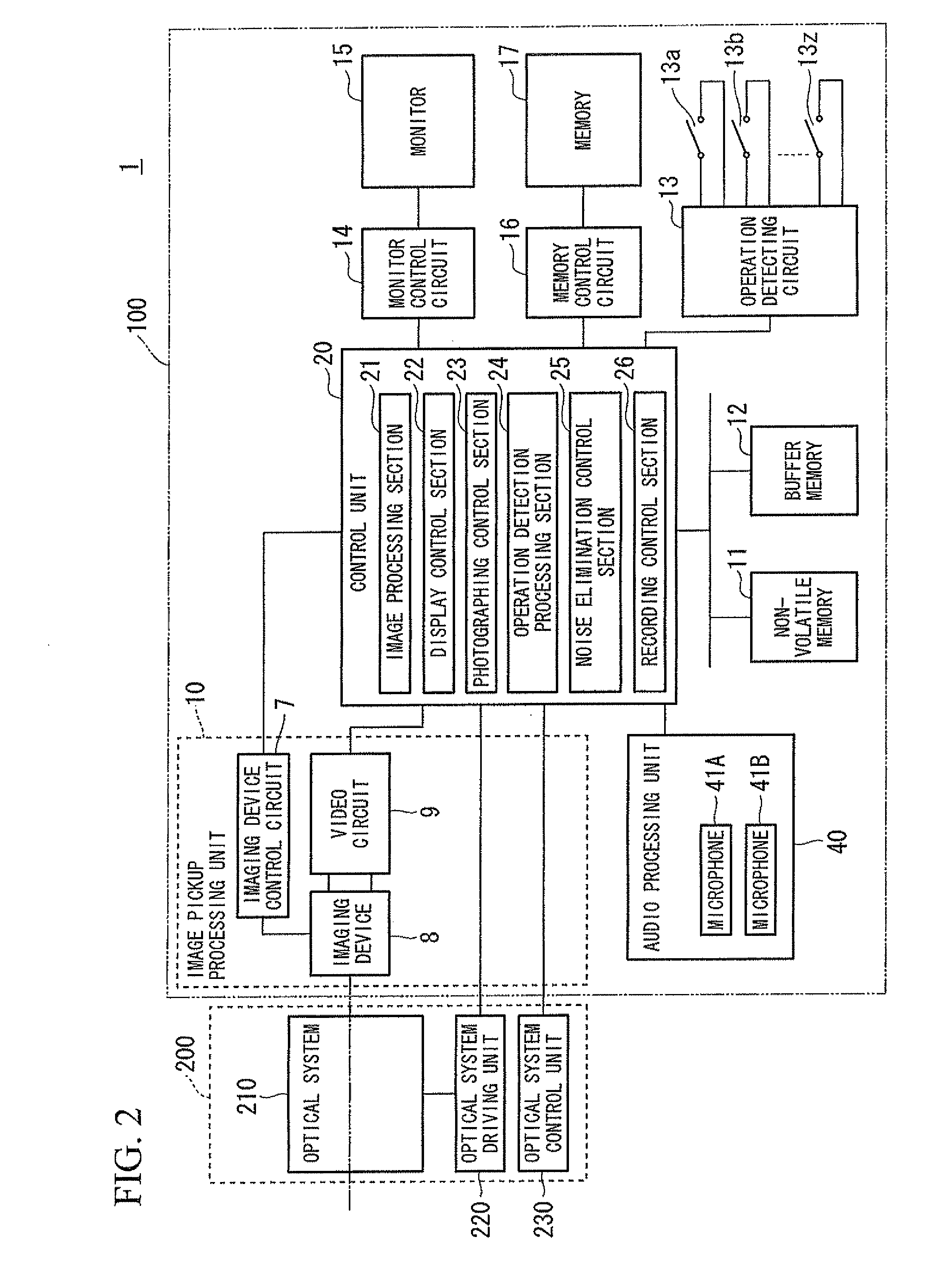
[0017]The image pickup apparatus 1 includes a camera main body 100 and a lens barrel 200 that is disposed on the camera main body 100 so as to be detachably attached thereto. The lens barrel 200 is mounted on the camera main body 100 through a lens mount that is disposed on the front face of the camera main body 100.
[0018]In addition, on the front face of the camera main body 100, a microphone 41A and a microphone 41B are disposed. The microphones 41A and 41B are disposed within a plane approximately perpendicular to the lens optical axis of the lens barrel 200, that is, the front face of the camera main body 100. The microphones 41A and 41B are arranged su...
second embodiment
[0074]An image pickup apparatus according to a second embodiment of the present invention will be described below with reference to the accompanying drawings.
[0075]FIG. 5A is a top view of an image pickup apparatus 1a according to the second embodiment of the present invention. FIG. 5B is a front view of the image pickup apparatus 1a. To each configuration that is the same as that shown in FIGS. 1A and 1B, the same reference sign is attached.
[0076]The image pickup apparatus 1a includes a camera main body 100a and a lens barrel 200 that is disposed on the camera main body 100a so as to be detachably attached thereto. The lens barrel 200 is mounted on the camera main body 100a through a lens mount that is disposed on the front face of the camera main body 100a.
[0077]In addition, on the front and rear faces of the camera main body 100a, a microphone 41Aa and a microphone 41Ba are disposed. The microphones 41Aa and 41Ba are disposed on a straight line that is approximately parallel to ...
third embodiment
[0082]An image pickup apparatus according to a third embodiment of the present invention will be described below with reference to the accompanying drawings.
[0083]FIG. 6 is a schematic block diagram representing another use of the image pickup apparatus 1a according to this embodiment. FIG. 6 shows a main configuration for performing a selection operation such as a mode setting. To each configuration that is the same as that shown in FIGS. 1A, 1B, 2, and 3, the same reference sign is attached.
[0084]When detecting a selection input operation, for example, in accordance with an operation of the selector button 13SEL, the operation detection processing section 24 (see FIGS. 1A and 1B) records information on the detected operation in the memory. The operation detection processing section 24 specifies the operated selector button 13SEL. Since the operated selector button 13SEL has a plate spring on the inside thereof, the plate spring reacts with the operation so as to be curved back. Th...
PUM
 Abstract
Description
Claims
Application Information