
Visual Identifier for Images on an Electronic Display

a technology of visual identifier and electronic display, which is applied in the field of light sensor, can solve the problems of loss of critical advertising exposure and possible revenue to the advertising firm, degraded performance of the most reliable electronic display, and premature failure of one or more components

Active Publication Date: 2011-04-28
MFG RESOURCES INT INC
View PDF24 Cites 22 Cited by
  • Summary
  • Abstract
  • Description
  • Claims
  • Application Information

AI Technical Summary

Benefits of technology

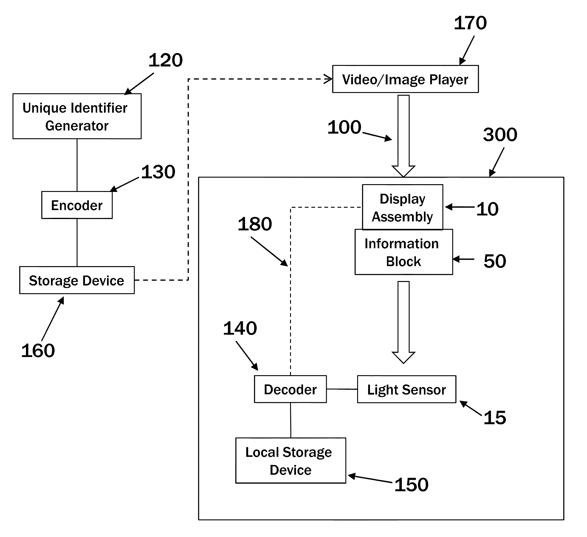
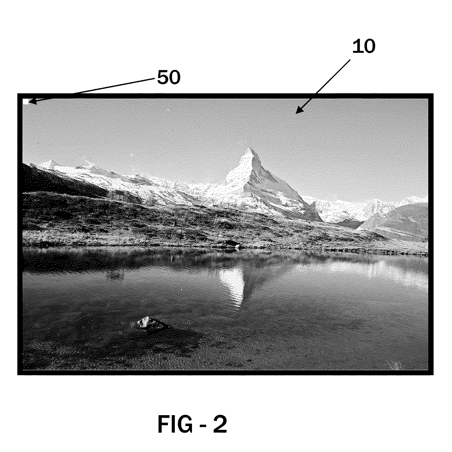
[0006]Exemplary embodiments create a unique identifier for each unique piece of video/image content. The unique identifier may be encoded and sent to a portion of the image-producing electronic display assembly (information block) for displaying simultaneously with the video/image content. The information block may be measured by a light sensor where this data is then decoded and stored. The decoded data can later be compared with the original unique identifier in order to confirm that the image was actually shown on the display and when. The unique identifier can be created in a number of ways, either manually, through

Problems solved by technology

Over many hours of use, even the most reliable electronic displays are known to degrade in performance or possibly have one or more components fail prematurely.
When a display is used for advertising purposes, a sudden failure or degradation in performance can result in the loss of critical advertising exposure and possible revenue to the advertising firm.
Further, when a display is used for information, a failure of the display may result in the loss of critical information such as flight schedules or emergency alerts.

Method used


Image

  • Visual Identifier for Images on an Electronic Display
  • Visual Identifier for Images on an Electronic Display
  • Visual Identifier for Images on an Electronic Display

Examples


first embodiment

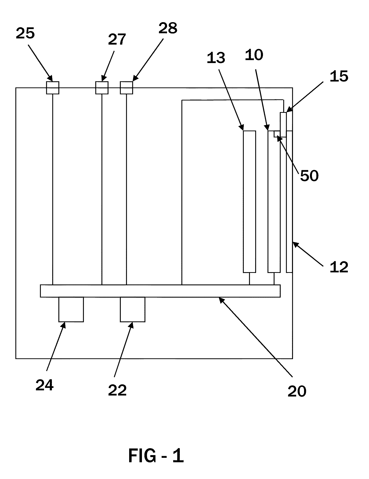
[0031]In a first embodiment, the light sensor 15 may simply be designed to interpret between black and white shapes. Thus, black may represent 0, white may represent 1, and the encoded unique identifier can be represented in this simple binary format to the light sensor 15.

second embodiment

[0032]In a second embodiment, the light sensor 15 may be designed to interpret between additional colors: red, blue, green, and white where each shade could take on a two bit value and represent 0, 1, 2, and 3 respectively. Any type of color light sensor could be used here while an exemplary color light sensor might be the TCS3404CS or TCS3414CS which are commercially available from Texas Advanced Optoelectronic Solutions® (TAOS) of Plano, Tex. www.taosinc.com. The TAOS specification document TAOS068 entitled TCS3404CS, TCS3414CS Digital Color Light Sensors' is herein incorporated by reference in its entirety.

third embodiment

[0033]In a third embodiment, the light sensor 15 may be a CCD camera and could thus interpret a matrix of time varying image elements in the information block 50. As is known in the art, the size of the light measurement elements of CCD cameras are typically much smaller than the size of pixel elements of electronic displays. Thus, a CCD camera (or similar type of light measurement device) could interpret several ‘data points’ (i.e. groupings of image pixels) simultaneously and could therefore transfer more data in the same amount of time.

[0034]Some embodiments may not report errors out to the user immediately, but instead may simply store the data internally for later retrieval by the user. In an exemplary embodiment, the performance data may be accessed by the user through a web browser which communicates with one of the network interfaces of the display. Once the data is retrieved and analyzed it may be determined that the display has malfunctioned and may continue to malfunction...


PUM


Abstract

A system and method for displaying images or video on an electronic display. A unique identifier may be embedded within the frames of images or video and detected by a light sensor. The data from the light sensor is analyzed to determine if the proper image or video was actually shown at the display. Some embodiments analyze the data from the light sensor in real time and may stop displaying the image or video if the data is not in the format of a unique identifier. Using this embodiment, the system can prevent unintended images or video from being shown on the display.

Description

CROSS-REFERENCE TO RELATED APPLICATIONS[0001]This application is a non-provisional patent application of U.S. Application No. 61 / 308,139 filed on Feb. 25, 2010 and is herein incorporated by reference in its entirety. This application is a continuation-in-part of U.S. application Ser. No. 12 / 706,594 filed Feb. 16, 2010 which is a non-provisional of U.S. Application No. 61 / 152,876 filed Feb. 16, 2009 each of which are hereby incorporated by reference in their entirety. This application is a continuation-in-part of U.S. application Ser. No. 12 / 706,602 filed Feb. 16, 2010 which is a non-provisional of U.S. Application No. 61 / 152,876 filed Feb. 16, 2009 each of which are hereby incorporated by reference in their entirety.TECHNICAL FIELD[0002]Exemplary embodiments generally relate to a light sensor placed in front of an electronic display to monitor actual display performance.BACKGROUND OF THE ART[0003]Electronic displays have previously been used predominantly in indoor entertainment app...

Claims


Application Information

Patent Timeline
IPC IPC(8): G06K9/64G09G5/00G09G3/36G09G3/30H04N5/66
CPCG09G3/006G09G2360/145H04N21/23892H04N21/8358H04N21/4223H04N21/44008H04N21/812H04N21/41415
Inventor DUNN, WILLIAMDE LAET, RICKSCHUCH, JOHNWASINGER, JERRY
Owner MFG RESOURCES INT INC
Learn More