Image forming apparatus

Inactive Publication Date: 2011-04-28
KYOCERA DOCUMENT SOLUTIONS INC
View PDF4 Cites 16 Cited by
  • Summary
  • Abstract
  • Description
  • Claims
  • Application Information

AI Technical Summary

Benefits of technology

[0060]According to the present aspects of the present invention, it is possible to provide an image forming apparatus in which, because the amount of static elimination light irradiated onto area

Problems solved by technology

Here, a state in which only external additives have been transferred onto the transverse surface of the former is one that it is difficult for the cleaning apparatus of the intermediate transfer medium to clean.
Moreover, a state in which the external additives have been transferred onto the cleaning blade of the latter is one that these areas are abraded by the external additives via the cleaning blade, thus the problem arises that the amount of wear on the photosensitive drum in these areas shortens the lifespan of the photosensitive drum.
Further, in a photosensitive drum which is made of, for example organic materials and thus is comparatively easily abraded, if it makes direct contact with a contact-charging type charging roller, adjacent edge portions of this charging roller deteriorate easily due to electrical discharge.
Specifically, if the shape of a charging roller is formed as a simple circular-cylinder shape with sharply outstanding ed

Method used


Image

  • Image forming apparatus
  • Image forming apparatus
  • Image forming apparatus

Examples


Embodiment Construction

[0075]An embodiment of the present invention will now be described based on the drawings.

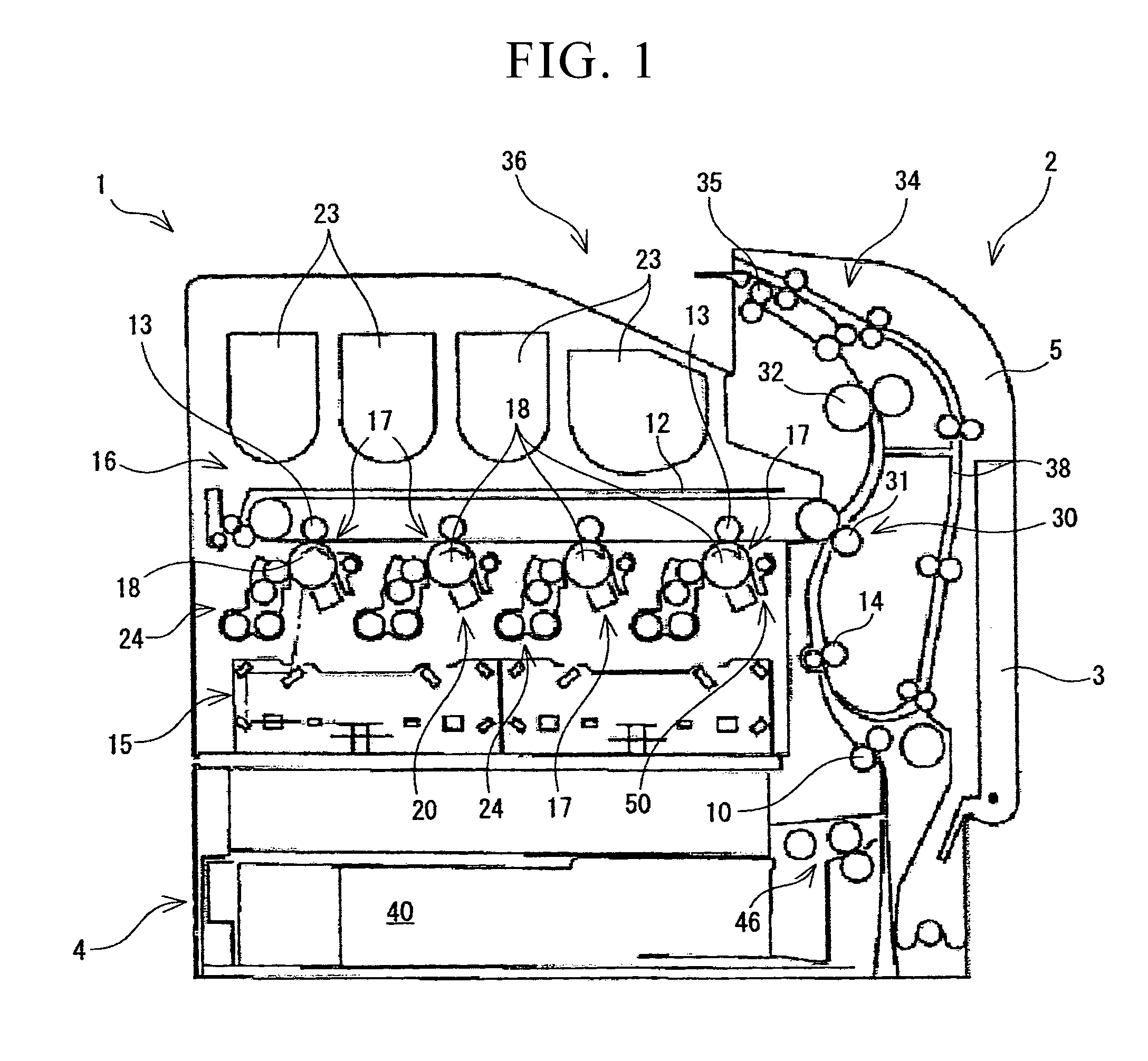
[0076]In FIG. 1, the structure of a printer 1 which is capable of color printing is shown schematically as an example of an image forming apparatus. The cross-section shown in this drawing is one viewed from the left side surface of the printer 1. Accordingly, the front surface of the printer 1 is located on the right side in FIG. 1, while the rear surface thereof is located on the left side.

[0077]As is shown in FIG. 1, a paper output tray 36 is provided above an apparatus main body 2 of the printer 1, and a front cover 5 in which a plurality of operating keys that are supplied for various operations performed by a user as well as a screen that displays a variety of information are arranged, are provided adjacent to this paper output tray 36.

[0078]In addition, a paper feed cassette 4 is located below the apparatus main body 2, and sheets of copy paper are housed in a stack in a housing portion 4...


PUM


Abstract

An image forming apparatus (1) forms a toner image by using toner which includes external additives to develop a latent image which is formed via charging and exposure on a surface of a photosensitive drum (18), and transfers the toner image onto a transfer material, and includes: a static elimination unit (19) that irradiates static elimination light onto the surface of the photosensitive drum before the surface of the photosensitive drum is charged, and removes any charge remaining on the surface of the photosensitive drum after it has completed the transfer; and a static elimination intensity adjustment device (74) that, compared with inner side areas of the paper feed width, lessens the amount of static elimination light irradiated onto areas which, when viewed in the direction of the rotation axis of the photosensitive drum, are on an outer side of the paper feed width and are also on an inner side of the developing width.

Description

BACKGROUND OF THE INVENTION[0001]1. Field of the Invention[0002]The present invention relates to an image forming apparatus that outputs a toner image on a photosensitive drum onto an intermediate transfer medium or copy paper.[0003]Priority is claimed on Japanese Patent Application No. 2009-244647, filed Oct. 23, 2009, and Japanese Patent Application No. 2010-039820, filed Feb. 25, 2010, the content of which is incorporated herein by reference.[0004]2. Description of Related Art[0005]In this type of image forming apparatus electrophotography is used. A charging unit preliminarily charges a photosensitive drum, and when an exposure section irradiates light onto the surface of the photosensitive drum, an electrostatic latent image is formed on this photosensitive drum surface. A developer supports a toner, and when a developing bias voltage is applied thereto, the toner becomes excited to adhere to the electrostatic latent image and a toner image is formed (i.e., developed) on the su...

Claims


Application Information

Patent Timeline
IPC IPC(8): H05F3/00
CPCG03G21/08
Inventor MIYAJI, SHINKI
Owner KYOCERA DOCUMENT SOLUTIONS INC
Why Eureka
Try Eureka