Variable air volume economizer minimum position reset

a technology of air volume economizer and minimum position, which is applied in ventilation systems, lighting and heating apparatus, heating types, etc., can solve problems such as insufficient ventilation air

Inactive Publication Date: 2011-04-28
CARRIER CORP
View PDF16 Cites 36 Cited by
  • Summary
  • Abstract
  • Description
  • Claims
  • Application Information

AI Technical Summary

Problems solved by technology

It has been recognized that with a variable indoor flow rate as with a VAV system and other zoning systems, the fixed minimum damper position would result in insufficient ventilation air when the indoor air flow rate is decreased below the design full load airflow.

Method used


Image

  • Variable air volume economizer minimum position reset
  • Variable air volume economizer minimum position reset
  • Variable air volume economizer minimum position reset

Examples


Embodiment Construction

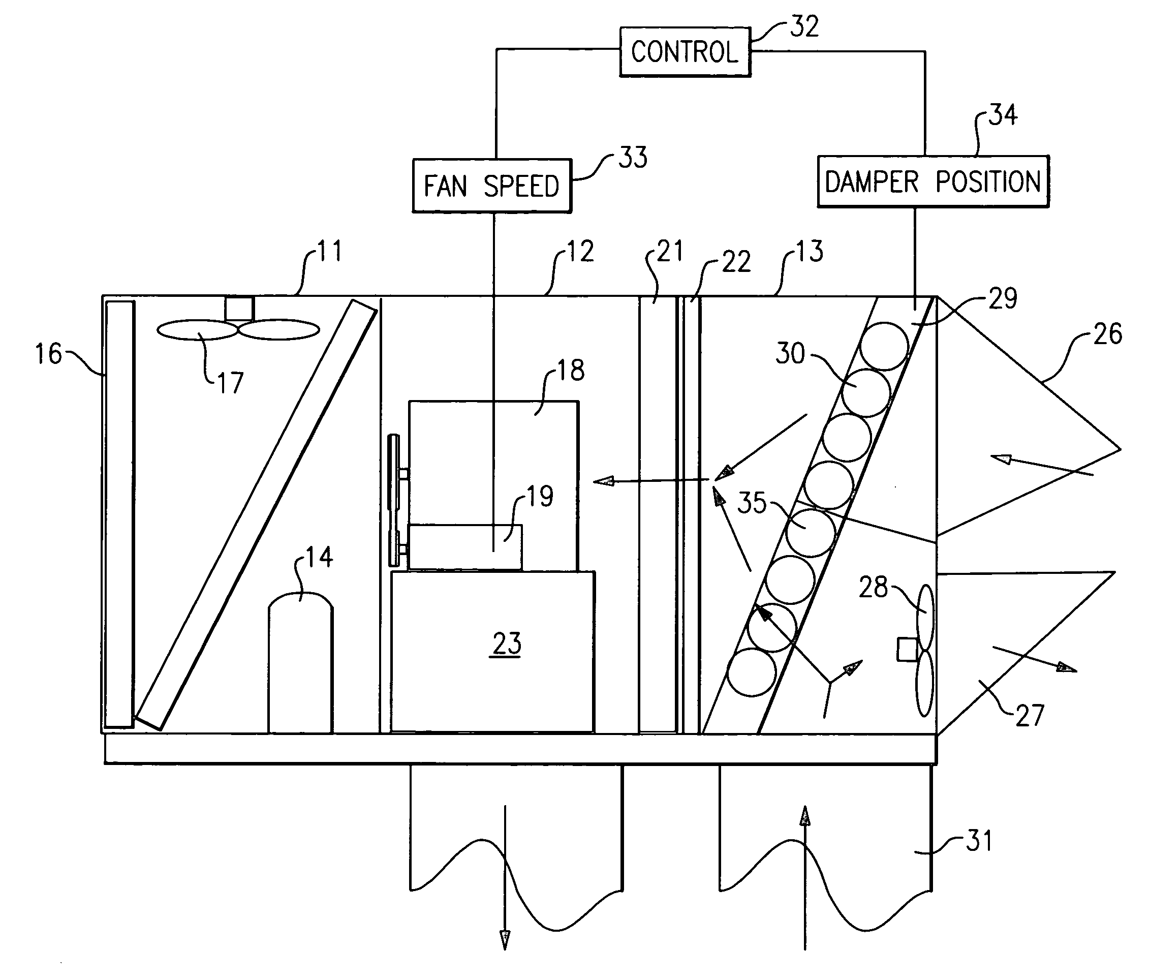
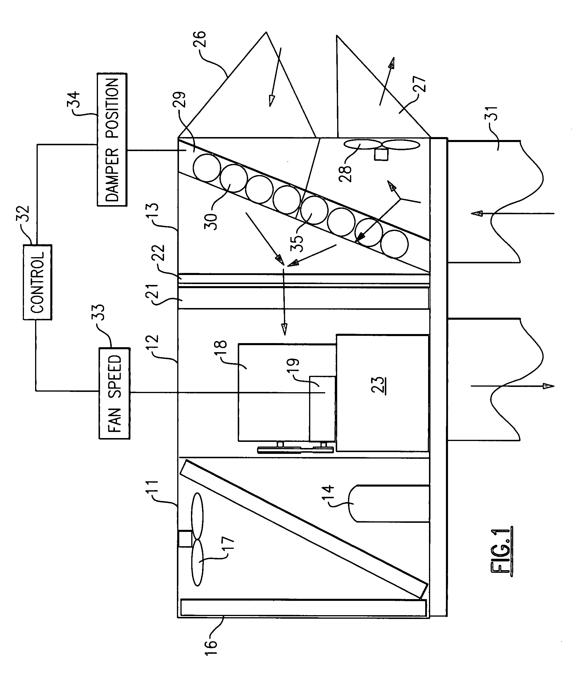
[0014]Shown in FIG. 1 is a typical packaged rooftop air conditioner having a condenser section 11, an evaporator section 12 and an economizer section 13. The condenser section 11 includes a compressor 14 for receiving refrigerant vapor from the evaporator section 12 and compressing the vapor before it is condensed. Also included in the condenser section 11 is a condenser coil 16 and a condenser fan 17 for passing ambient air through the condenser coil 16.

[0015]The evaporator section 12 includes a supply fan 18 which is driven by a fan motor 19. The fan motor is adapted to operate at variable speeds to meet the cooling / heating requirements of the system. One manner of providing the variable speed is by the use of an inverter for providing variable frequency power to the fan motor 19.

[0016]Leading into the evaporator section 12 from the economizer section 13 is a cooling coil 21 and its associated filters 22. A heater 23 is placed in a downstream position from the supply fan 18. In op...


PUM


Abstract

A rooftop air conditioner having a variable speed fan and an economizer also includes a control feature for adjusting the minimum damper position in response to the speed of the fan during predetermined conditions in order to maintain a desired volume of fresh air from the economizer.

Description

TECHNICAL FIELD[0001]This invention relates generally to variable air volume air conditioning systems and, more particularly, to a system for operating the economizer damper therein to ensure sufficient outside air is introduced in order to meet minimum ventilation code requirements.BACKGROUND OF THE INVENTION[0002]In a typical climate control system of a building, a central thermostat controls the temperature of air in the building. A building central heating / cooling unit forces a constant amount of heated or cooled air to various points in the building through duct work comprising a supply air duct, a plurality of zone ducts and a return air duct.[0003]In variable air volume (VAV) systems the space temperature is controlled by varying the airflow delivered to the space. This is done by means of a variable speed fan controlled by a variable frequency inverter, the position of inlet dampers to the fan or other airflow control devices. For larger or by varying VAV systems, individual...

Claims


Application Information

Patent Timeline
Patent Type & Authority Applications(United States)
IPC IPC(8): F24F7/007
CPCF24F11/0079F24F13/14Y02B30/746F24F2011/0006F24F2011/0002F24F11/77Y02B30/70
Inventor LORD, RICHARD G.
Owner CARRIER CORP
Why Eureka
Try Eureka