Large, Ultra-Thin And Ultra-Light Connectable Display For A Computing Device

a computing device and connectable display technology, applied in the field of digital image devices, can solve the problems of difficulty in creating video images, difficulty in adjusting the resolution of the display screen,

Inactive Publication Date: 2011-04-28
LABLANS PETER
View PDF81 Cites 105 Cited by
  • Summary
  • Abstract
  • Description
  • Claims
  • Application Information

AI Technical Summary

Problems solved by technology

This method is not very user friendly or requires complex cameras or complex camera settings.
Furthermore, this method may be troublesome for creating video images.
The quality and the size of such integrated display screens is generally barely adequate and mainly ...

Method used


Image

  • Large, Ultra-Thin And Ultra-Light Connectable Display For A Computing Device
  • Large, Ultra-Thin And Ultra-Light Connectable Display For A Computing Device
  • Large, Ultra-Thin And Ultra-Light Connectable Display For A Computing Device

Examples


Embodiment Construction

mera in rear view in accordance with yet a further aspect of the present invention;

[0018]FIGS. 11-13 are diagrams of a camera in frontal view in accordance with one or more aspects of the present invention;

[0019]FIG. 14 is a diagram of a carrier of lens / sensor units for a camera for stereoscopic and or 3D images in accordance with an aspect of the present invention;

[0020]FIG. 15 is a diagram of a carrier of lens / sensor units for a camera for stereoscopic and or 3D images in accordance with another aspect of the present invention;

[0021]FIG. 16 is a diagram of a carrier of lens / sensor units for a camera for stereoscopic and or 3D images in accordance with yet another aspect of the present invention;

[0022]FIG. 17 is a diagram of a system having a camera and a display in accordance with an embodiment of the present invention;

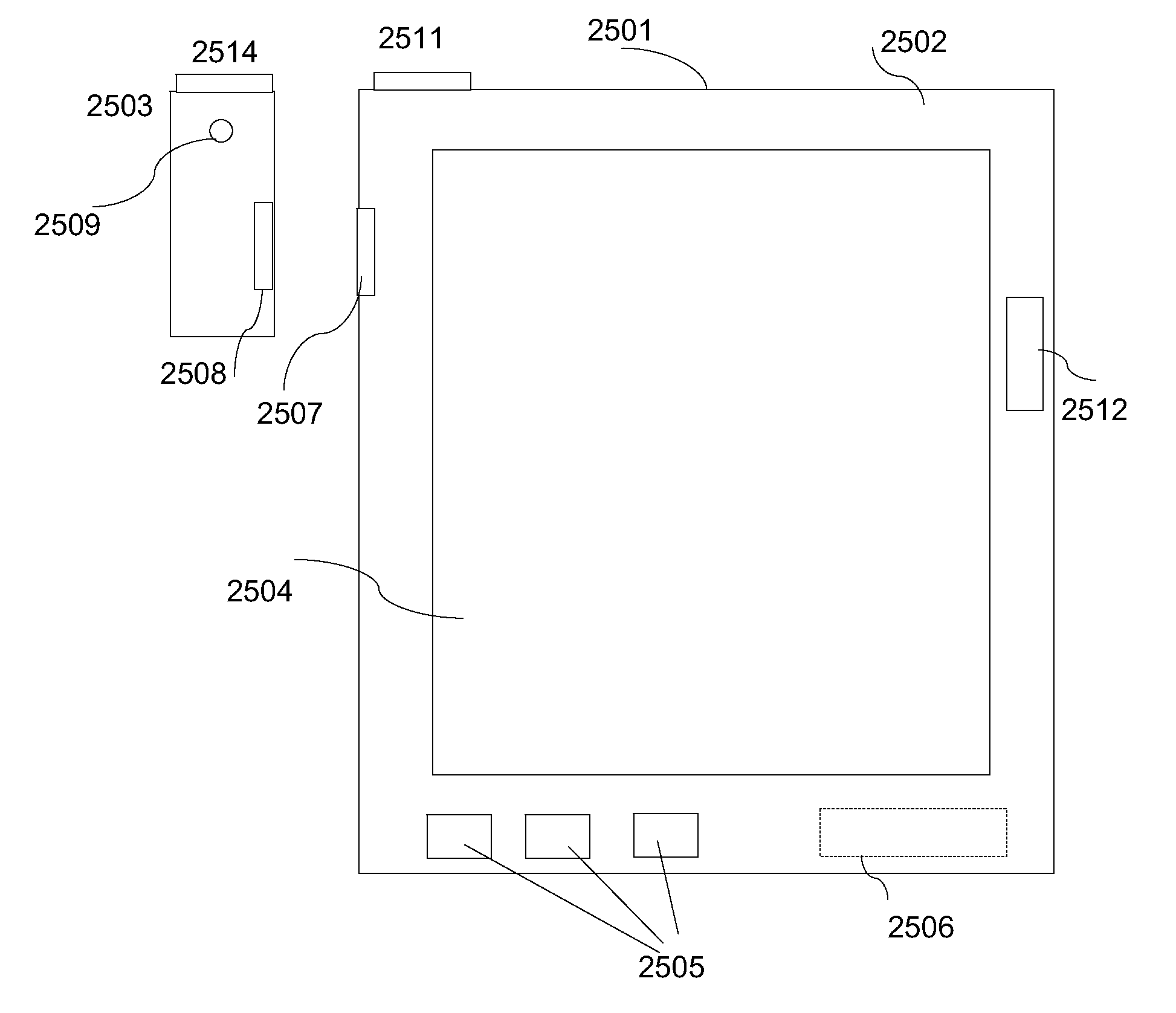
[0023]FIG. 18 is a computing device in accordance with an aspect of the present invention;

[0024]FIGS. 19-21 are diagrams of a camera with a thin large sized display...


PUM


Abstract

Methods and apparatus to create and display screen stereoscopic and panoramic images are disclosed. Methods and apparatus are provided to generate multiple images that are combined into a stereoscopic or a panoramic image. An image may be a static image. It may also be a video image. A controller provides correct camera settings for different conditions. An image processor creates a stereoscopic or a panoramic image from the correct settings provided by the controller. A plurality of lens/sensor units is placed on a carrier. Lens/sensor units are rotationally aligned. A controller rotationally aligns images of lens/sensor units that are rotationally misaligned. The camera is enabled to communicate via a wired or via a wireless connection, with a separate, mobile, ultrathin, ultralight, display with a large display screen not smaller than 25 by 20 cm in a first embodiment of the present invention and not smaller than 20 by 15 cm in a second embodiment of the present invention to provide color images including video images in real-time. A compact controllable platform to hold and rotate a device with a lens/sensor unit is also provided.

Description

STATEMENT OF RELATED CASES[0001]This application is a continuation-in-part of U.S. Non-provisional patent application Ser. No. 12 / 634,058 filed on Dec. 9, 2009, which is a continuation-in-part of U.S. Non-provisional patent application Ser. No. 12 / 538,401 filed on Aug. 10, 2009, which are all incorporated herein by reference in their entirety. application Ser. No. 12 / 538,401 claims the benefit of U.S. Provisional Patent Application Ser. No. 61 / 106,025, filed Oct. 16, 2008, and of U.S. Provisional Patent Application Ser. No. 61 / 106,768, filed Oct. 20, 2008, which are both incorporated herein by reference in their entirety. This application also claims the benefit of U.S. Provisional Patent Application Ser. No. 61 / 291,861, filed on Jan. 1, 2010, of U.S. Provisional Patent Application Ser. No. 61 / 322,875, filed on Apr. 11, 2010, and of U.S. Provisional Patent Application Ser. No. 61 / 365,347, filed on Jul. 18, 2010 which are all incorporated herein by reference in their entirety. This a...

Claims


Application Information

Patent Timeline
IPC IPC(8): H04W88/02H04N5/44H04N5/222H04M1/72409H04M1/72412H04N13/239
CPCG03B35/00H04M1/72527H04M1/7253H04N13/0246H04N5/23238H04N5/2624H04N13/0239H04M2250/16H04N13/239H04N13/246H04M1/72409H04M1/72412H04N23/698
Inventor LABLANS, PETER
Owner LABLANS PETER
Why Eureka
Try Eureka