Artificial surfing facility

a technology of artificial surfing and fixed structures, which is applied in the field of transportable or fixed artificial surfing facilities, can solve the problems of less variability in respect to fixed internals and increased costs

Active Publication Date: 2011-05-05
ACTION TEAM VERANSTALTUNGS
View PDF13 Cites 21 Cited by
  • Summary
  • Abstract
  • Description
  • Claims
  • Application Information

AI Technical Summary

Benefits of technology

[0009]It is advantageously provided that several pump units located next to one another are upstream of the flow section. The flow section constitutes a relatively large reservoir which homogenizes the amount of water which has been delivered by the different pump units. In this way, at a smaller water demand, to produce a lower wave which is suitable for beginning surfers, for example, individual pumps can also be throttled in their delivery rate or turned completely off without this leading to a different layer thickness of the water flow, viewed over the width of the ramp.
[0010]The side walls of the flow section and likewise also the side walls in the region of the ramp can optionally be arranged preferably to form a constriction to whose width preferably the wave pool, with side walls which can be moved relative to one another, can also be adapted. In addition to regulating the amount of water delivery, this yields further possibilities of influencing the standing wave. Thus, adaptation of its height for various performance levels of the surfer is also possible.
[0011]In a mobile surfing facility with a limited amount of circulating water, it is especially advantageous if the wave pool, the pump chambers, and the collecting space are surrounded by a main pool. Separation of the wave pool which is located higher than the main pool, moreover, ensures that only a defined mass of water—specifically that in the wave pool—forms the resistance for the water flowing down the ramp. Formation of the standing wave can thus be computed much better and can be more uniquely reproduced.

Problems solved by technology

Fixed internals mean increased cost and offer less variability with respect to the shape and height of the resulting wave.

Method used


Image

  • Artificial surfing facility
  • Artificial surfing facility
  • Artificial surfing facility

Examples


Embodiment Construction

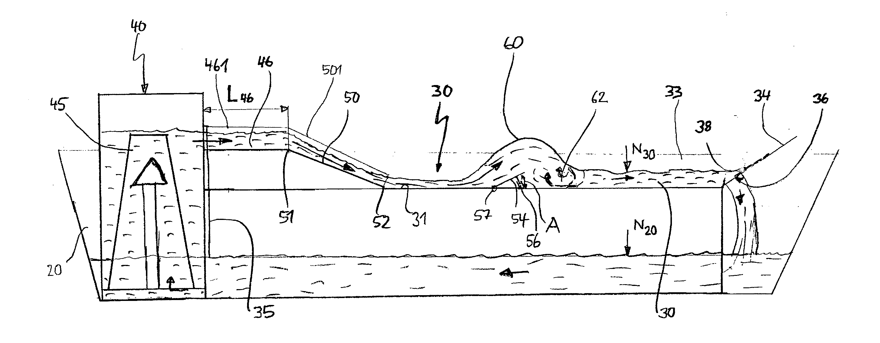
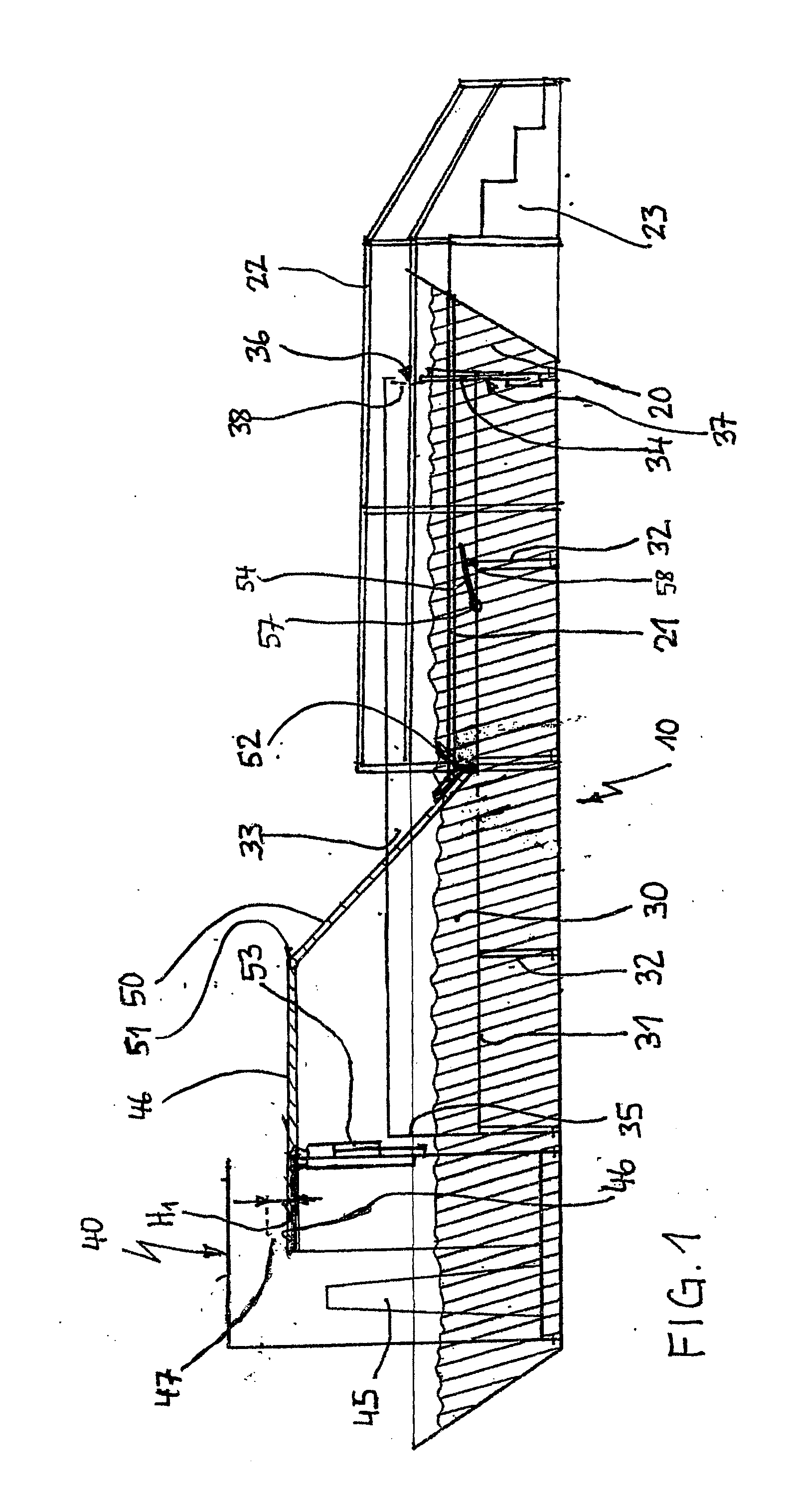
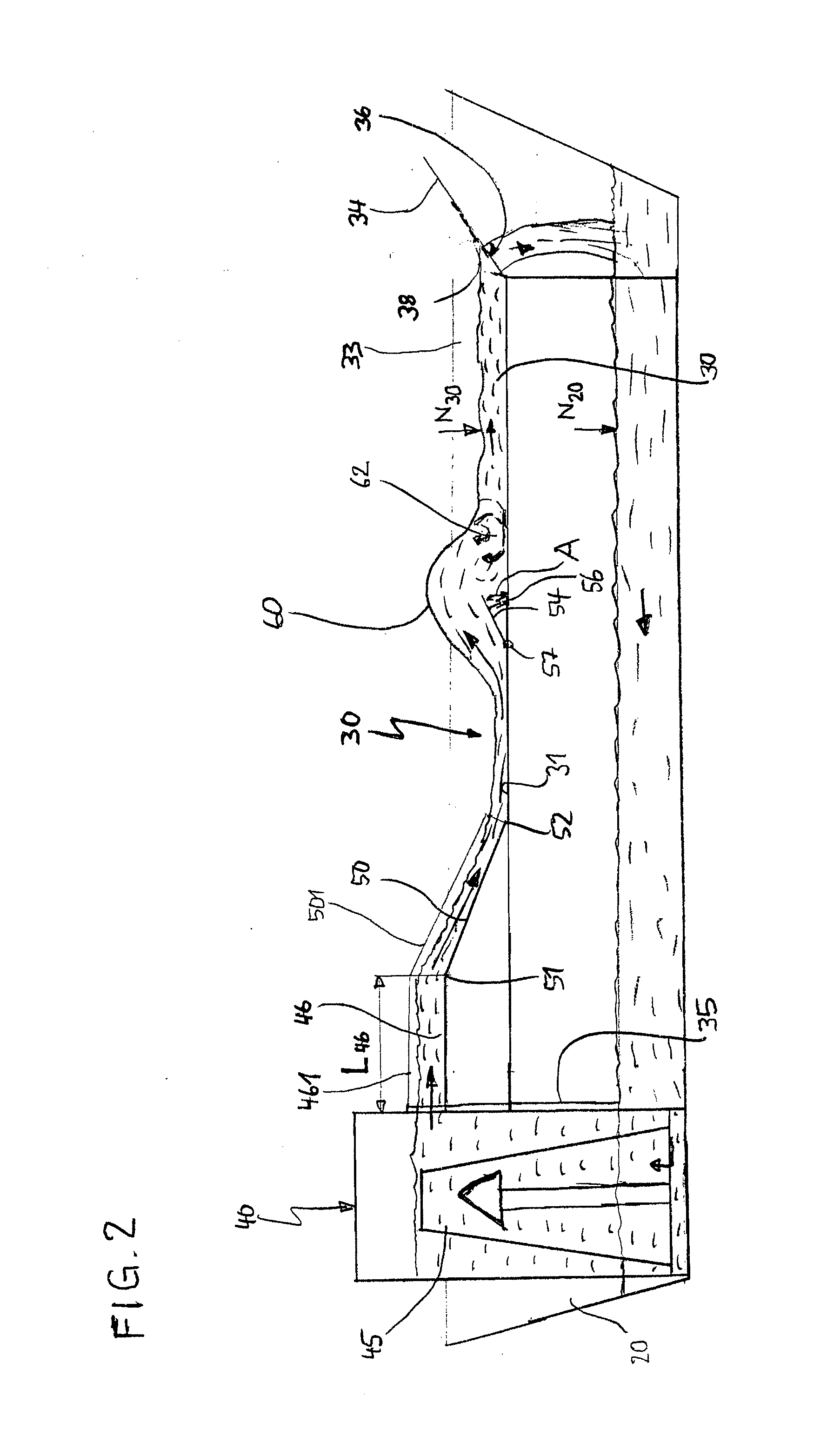
[0027]The figures are purely schematic and should in no case be regarded as to scale. The surfing facility 10 shown in FIGS. 1 to 3 is formed by a trough-shaped main pool 20 which holds all other components and keeps the water necessary for operation of the surfing facility 10 in a closed circuit. Within the main pool 20, opposite its bottom, is a wave pool 30 elevated on supports 32. The wave pool 30, aside from the part of the main pool 20 which is on the left in the figures, extends over most of the length and width of the main pool 20 (see, FIG. 2). However, as a result of the bottom 31 of the wave pool 30, which is elevated relative to the main pool 20, the wave pool 30 has a much lower depth. The water mass in the wave pool 30 is accordingly smaller than the total water mass of the main pool 20. The wave pool 30, on either side, is bordered by two side walls 30, by a rear wall 34 (shown on its right side) and by a front wall 35 (shown on its left side). In the rear wall 34, an...


PUM


Abstract

An artificial surfing facility for producing a standing wave, with an inclined ramp, to the upper end of which water is conveyed by at least one pump and at the lower end of which the water discharges into a wave pool. A standing wave is easily attained by there being an adjustable guide device in the wave pool at a distance from the bottom end of the ramp in the flow direction as a wave initiator. The wave pool, during operation of at least one pump, has a liquid level which is located above the liquid level of a main pool which surrounds the wave pool and the amount of water in the wave pool offers a defined resistance to the water flowing down the ramp so that the formation and height of the standing wave are influenced by the change of the flow velocity.

Description

BACKGROUND OF THE INVENTION[0001]1. Field of the Invention[0002]The invention relates to a transportable or fixed artificial surfing facility for producing a standing wave with an inclined ramp to whose upper end water is conveyed over a flow section by means of at least one pump and whose lower end discharges the water into a wave pool.[0003]2. Description of Related Art[0004]A surfing facility of the type indicated above is known from U.S. Pat. No. 6,019,547. In it, the water flows down a fixed inclined plane and strikes two stationary flow-shaping elements that are arranged spaced apart from one another in succession and produce a standing wave on a rising flank of the second element. Fixed internals mean increased cost and offer less variability with respect to the shape and height of the resulting wave.SUMMARY OF THE INVENTION[0005]The object of the invention is to devise an artificial surfing facility by means of which standing waves of various shape and height can be produced...

Claims


Application Information

Patent Timeline
Patent Type & Authority Applications(United States)
IPC IPC(8): A47K3/10
CPCA63B69/0093A63G31/007A63B2208/03A63C19/00A63B2225/60A63B2225/093A63B71/023A63B2225/09A63B71/0054E04H4/0006
Inventor KLIMASCHEWSKI, RAINER
Owner ACTION TEAM VERANSTALTUNGS
Why Eureka
Try Eureka