Eureka AIR delivers breakthrough ideas for toughest innovation challenges, trusted by R&D personnel around the world.

A method of expanding a tubular and expandable tubular

a tubular and well technology, applied in the direction of fluid removal, lubricant composition, borehole/well accessories, etc., can solve the problems of poor or lack of lubrication, field failure, loss of well, etc., and achieve the effect of reducing inadvertent or premature scraping, high and low surface roughness

Active Publication Date: 2018-07-05
SHELL USA INC
View PDF22 Cites 13 Cited by
  • Summary
  • Abstract
  • Description
  • Claims
  • Application Information

AI Technical Summary

Benefits of technology

The patent describes a method for improving the surface roughness of the inner surface of a tubular member to enhance lubrication during expansion. By increasing surface roughness, a larger reservoir of lubricant can be provided at the interface where contact forces apply, while maintaining the plastic deformation of the tubular member. In some embodiments, the lubricating layer is a corrosion inhibiting layer, which can be applied without needing to remove the corrosion inhibiting coating. The expansion member used during the expansion process has a smooth surface to minimize the forces required for plastic deformation of the asperities due to surface roughness of the inner tubular and for macroscopic deformation due to transverse expansion of the tubular. The technical effects of this invention include improved lubrication, reduced friction, and reduced damage to the tubular during expansion.

Problems solved by technology

Experience with commercially available lubricating coatings has indicated that they have shortcomings that may result in poor or lack of lubrication, which may lead to field failure with catastrophic consequences such as: stick slick phenomena, galling, overpull or expansion pressure increase, pipe rupture and eventually stuck expansion cones and / or other well equipment.
These conditions can lead to sidetracking and, in the worst case scenario, losing the well.

Method used


Image

  • A method of expanding a tubular and expandable tubular
  • A method of expanding a tubular and expandable tubular
  • A method of expanding a tubular and expandable tubular

Examples


Embodiment Construction

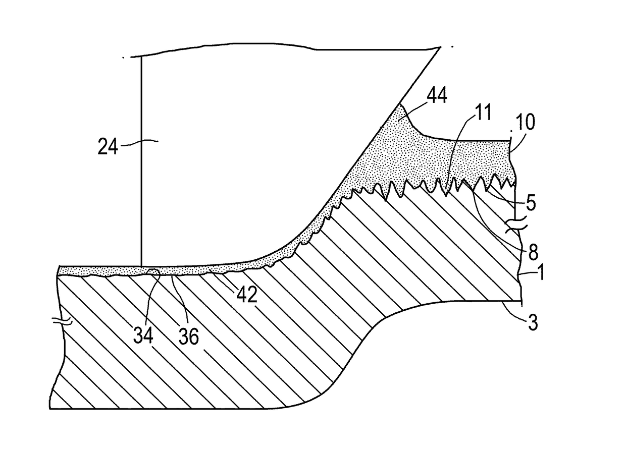
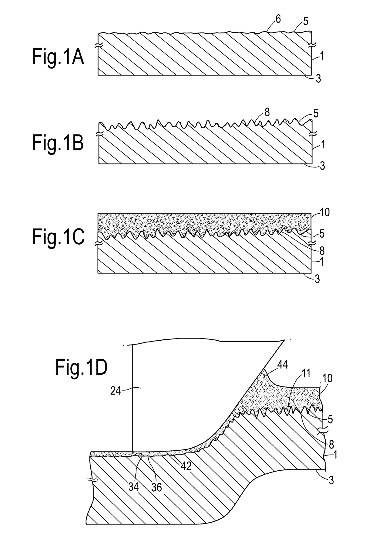
[0021]By a limited increased of the surface roughness, a larger reservoir of lubricant can be provided directly at the interface where contact forces apply during expansion while such limited increase in surface roughness does not substantially hamper the plastic deformation by an expansion member.

[0022]In some embodiments, the lubricating layer is a corrosion inhibiting layer. Metal tubulars such as steel tubulars are typically provided with a corrosion inhibiting coating shortly after production, so as to prevent e.g. rust formation during storage until use. When the layer contains both lubricating and corrosion inhibiting components, it is not needed to remove the corrosion inhibiting coating before applying the lubricating layer.

[0023]In some embodiments, the lubricating layer comprises one or more solid or thixotropic components selected from molybdenum di-sulfide, polytetrafluorethylene, graphite, sodium compounds, calcium compounds, zinc compounds, manganese compounds, and / or...


PUM

PropertyMeasurementUnit
surface roughnessaaaaaaaaaa
temperaturesaaaaaaaaaa

Abstract

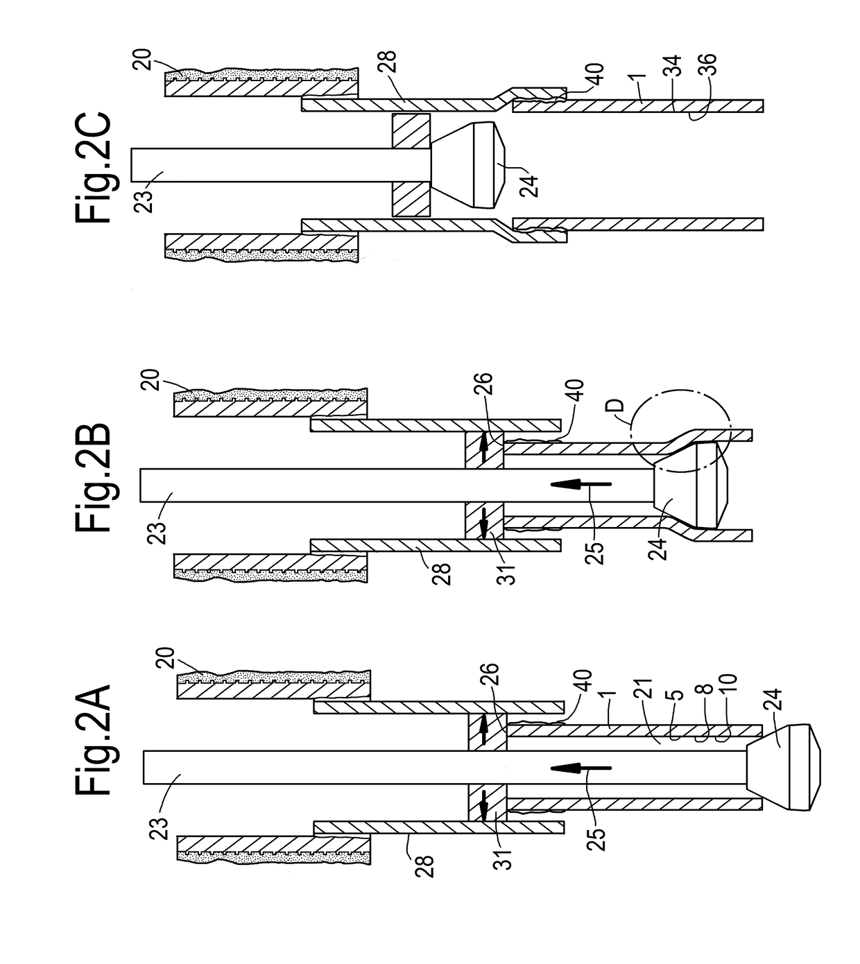
A tubular member (1) with a relative rough (1.5-10 μm) inner surface (5) coated solid lubricating film (10) which is transformed into a substantially viscous rubbery viscoelasto-plastic phase at temperatures in a range between 50° C. and 110° C. is expanded by moving an expansion member (24) with a relatively smooth outer surface (roughness <1.5 μm) therethrough, such that during expansion a viscous viscoelastoplastic substantially rubbery lubricating film (44) is generated between the tubular member (1) and the expansion mandrel (24), which film remains bonded to the rough inner surface (5) of the expanded tubular (1), but does not stick to the relatively hot and smooth expansion member (24).

Description

BACKGROUND OF THE INVENTION[0001]The present invention relates to a method of expanding a tubular member, and to an expandable well tubular.[0002]Wellbores for the production of hydrocarbon fluid are typically provided with steel casings and / or liners to provide stability to the wellbore wall and to prevent undesired flow of fluid between the wellbore and the surrounding earth formation. A casing typically extends from surface into the wellbore, whereas a liner may extend only in a lower portion of the wellbore. However in the present description the terms “casing” and “liner” are used interchangeably and without such intended difference.[0003]In a conventional wellbore, the wellbore is drilled in sections whereby each section is drilled using a drill string that has to be lowered into the wellbore through a previously installed casing section. In view thereof the wellbore and the subsequent casing sections decrease in diameter with depth. The production zone of the wellbore therefo...

Claims


Application Information

Patent Timeline
Patent Type & Authority Applications(United States)
IPC IPC(8): E21B43/10C10M169/04E21B43/30
CPCE21B43/106E21B43/105C10M169/04E21B43/108E21B43/30C10N2280/00C10N2230/12C10M169/00E21B43/103C10M2205/14C10M2207/126C10N2030/12C10N2050/02C10N2080/00
Inventor DI CRESCENZO, DANIELESHUSTER, MARK MICHAELZIJSLING, DJURRE HANSBOSMAN, ROB
Owner SHELL USA INC
Why Eureka
Eureka Blog
Learn More