
Piezoelectric motor

Inactive Publication Date: 2011-05-05
SAMSUNG ELECTRO MECHANICS CO LTD
View PDF4 Cites 0 Cited by
  • Summary
  • Abstract
  • Description
  • Claims
  • Application Information

AI Technical Summary

Benefits of technology

[0011]The present invention has been made in an effort to provide a piezoelectric motor which can minimize a problem in which vibration characteristics vary attributable to contact between a contact member and an electrode pattern of a piezoelectric vibrating body.

Problems solved by technology

The weight variation of the contact members 12 stimulates the electrode patterns and thus affects the driving frequency of the piezoelectric motor 10, thereby making the electric operation and control of the piezoelectric motor 10 difficult.
However, because of the recent trend of reducing the size of the piezoelectric motor 10, it is very difficult to change the position of the electrode pattern, so that the degree of freedom in printing of the electrode pattern is markedly reduced.

Method used


Image

  • Piezoelectric motor
  • Piezoelectric motor
  • Piezoelectric motor

Examples


first embodiment

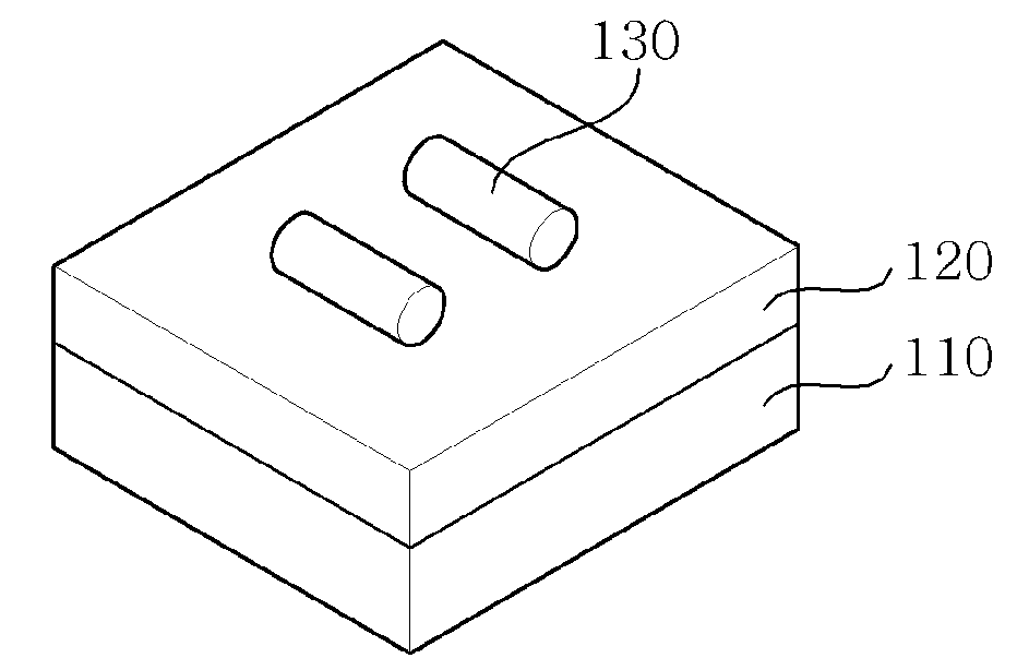
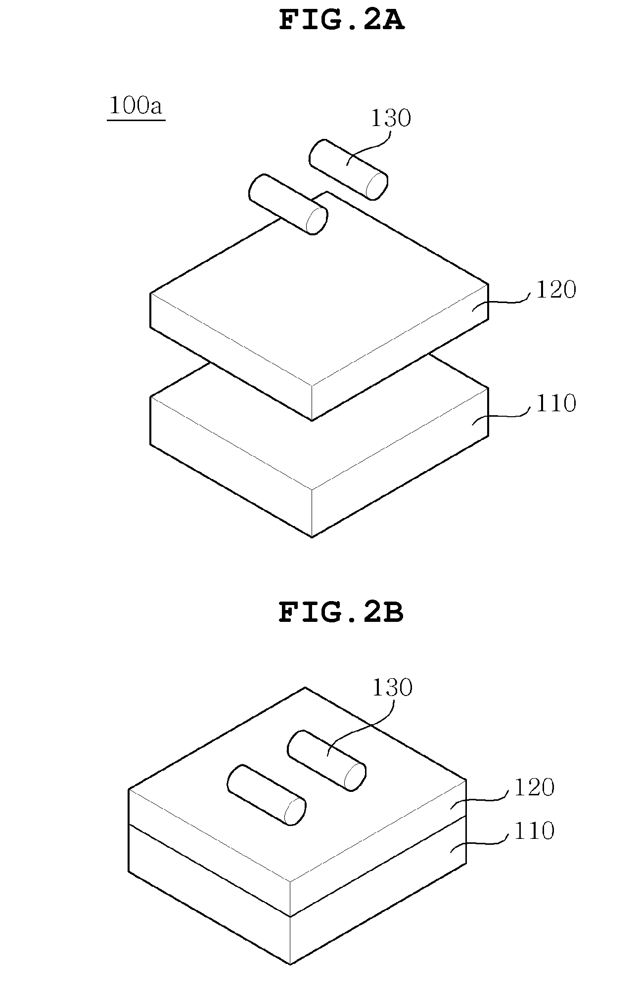
[0034]As shown in FIGS. 2A through 2C, the piezoelectric motor 100a includes a piezoelectric vibrating body 110, a dummy piezoelectric sheet layer 120 and contact members 130.

[0035]The piezoelectric vibrating body 110 generates vibrations (provides a vibration mode) using the change in shape when power is applied thereto. The piezoelectric vibrating body 110 is configured such that piezoelectric sheets (piezoelectric ceramic sheets) on which electrode patterns are formed are stacked one on top of another. Here, to when the electrode patterns printed on the surfaces of the piezoelectric sheets are appropriately set, the piezoelectric vibrating body 110 can provide a first vibration mode and a second vibration mode, for example, an elongation vibration mode which generates vibrations in the longitudinal direction of the piezoelectric vibrating body 110, and a bending vibration mode which generates vibrations in the thickness direction of the piezoelectric vibrating body 110. Here, th...

second embodiment

[0039]As shown in FIGS. 3A through 3C, in the piezoelectric motor 100b recesses 125 are formed in a dummy piezoelectric sheet layer 120 to predetermined depths in the thickness direction thereof. Contact members 130 are provided on the dummy piezoelectric sheet layer 120 in such a way that portions of the contact members 130 are embedded in the recesses 125. As such, in the case where the contact members 130 are partially embedded in the recesses 125, a problem of weight variation of the contact members 130 when attached to the dummy piezoelectric sheet layer 120 affecting the driving frequency of the piezoelectric motor 100b can be minimized Therefore, the piezoelectric motor 100b can be effectively operated / controlled. Furthermore, a contact area between the dummy piezoelectric sheet layer 120 and the contact members 130 increases, so that the intensity with which the contact members 130 are attached to the dummy piezoelectric sheet layer 120 can increase. In addition, because th...


PUM


Abstract

Disclosed herein is a piezoelectric motor. The piezoelectric motor includes a piezoelectric vibrating body, a dummy piezoelectric sheet layer and a contact member. The piezoelectric vibrating body is configured such that piezoelectric sheets on which electrode patterns are printed are stacked on one on another. The dummy piezoelectric sheet layer is provided on the piezoelectric vibrating body. The contact member is provided on the outer surface of the dummy piezoelectric sheet layer. The contact member transmits vibrations generated from the piezoelectric vibrating body to the outside. Therefore, the piezoelectric motor can minimize a problem in which vibration characteristics vary attributable to contact between a contact member and an electrode pattern of a piezoelectric vibrating body.

Description

CROSS REFERENCE TO RELATED APPLICATION[0001]This application claims the benefit of Korean Patent Application No. 10-2009-0104228, filed Oct. 30, 2009, entitled “Piezoelectric motor”, which is hereby incorporated by reference in its entirety into this application.BACKGROUND OF THE INVENTION[0002]1. Technical Field[0003]The present invention relates to a piezoelectric motor.[0004]2. Description of the Related Art[0005]Recently, as a substitute for electromagnetic motors, piezoelectric motors (piezoelectric ultrasonic motors) using piezoelectric material have gained popularity. In piezoelectric motors, a piezoelectric vibrating body generates high frequency vibrations of a fine amplitude and transmits the vibrations to a slider (or rotor) which is in contact with a contact member attached to the piezoelectric vibrating body, thus enabling the slider to conduct fine motion. Compared to prior electromagnetic motors, such a piezoelectric motor has many advantages in that it can be reduced...

Claims


Application Information

Patent Timeline
IPC IPC(8): H02N2/04
CPCH01L41/0906H02N2/004H02N2/0065H02N2/00H02N2/04H10N30/202
Inventor HWANG, JUNG WOOKLEE, GUI YOUNSEOK, JUNGKO, HYUN PHILL
Owner SAMSUNG ELECTRO MECHANICS CO LTD
Features
  • Generate Ideas
  • Intellectual Property
  • Life Sciences
  • Materials
  • Tech Scout
  • Unparalleled Data Quality
  • Higher Quality Content
  • 60% Fewer Hallucinations
Learn More