
Tack for spine fixation

a technology for fixing the spine and a clamping device, which is applied in the direction of surgical staples, prostheses, ligaments, etc., can solve the problems and achieve the effect of extreme non-invasive apparatus and surgery methods

Inactive Publication Date: 2011-05-05
DOERR TIMOTHY E
View PDF59 Cites 8 Cited by
  • Summary
  • Abstract
  • Description
  • Claims
  • Application Information

AI Technical Summary

Benefits of technology

[0009]It is important and surprising that the preferred embodiments of posterior spine fixation apparatus consist essentially of, and preferably consist only of, one or more tacks inserted into facets of the facet joints, to extend across one or more facet joints of the spine to fix said facet joints. In other words, preferably only said tacks are used to make the facets of the selected facet joint(s) substantially or entirely immovable relative to each other, so that said the vertebra(e) / sacrum of the spine no longer bend / move relative to each other at said selected facet joint(s). The preferred embodiments of posterior spine fixation, therefore, do not include any additional structure implanted into the body, for example, no bars, no plates, no screws, or other structure extending between portions of the vertebra(e) and / or sacrum, or from vertebra to vertebra, or from vertebra to sacrum. The preferred apparatus is surprising effective and its simplicity results in extremely non-invasive apparatus and surgery methods.

Problems solved by technology

The preferred apparatus is surprising effective and its simplicity results in extremely non-invasive apparatus and surgery methods.

Method used


Image

  • Tack for spine fixation
  • Tack for spine fixation
  • Tack for spine fixation

Examples


Embodiment Construction

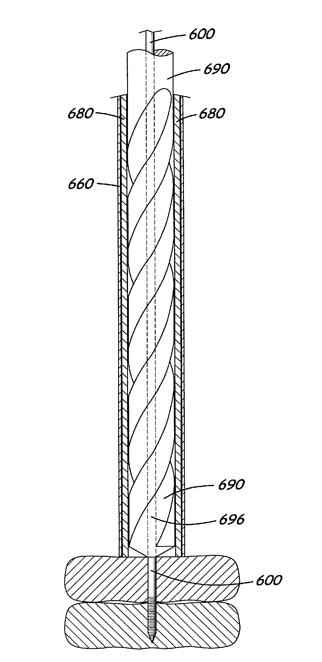
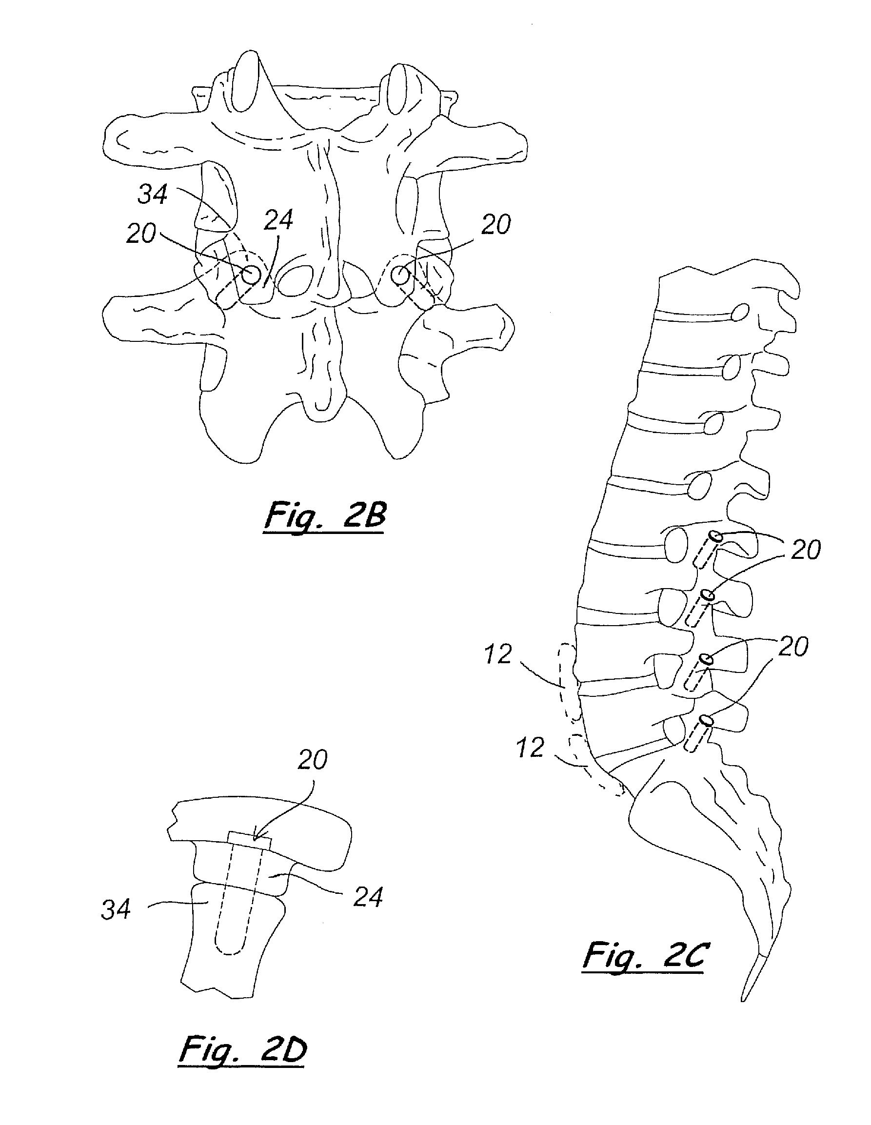
[0037]Referring to the Figures, there are shown several, but not the only, embodiments of the invented tack and methods, which are preferred for spine fixation and which may be used in various locations along the lumbar region of the spine, for example. Embodiments of the invented tacks may be used in other locations in the body, for example, wherein the tack may fix two portions of bone relative to each other or wherein the tack may be an anchor placed into a bone for attaching other structure to the bone.

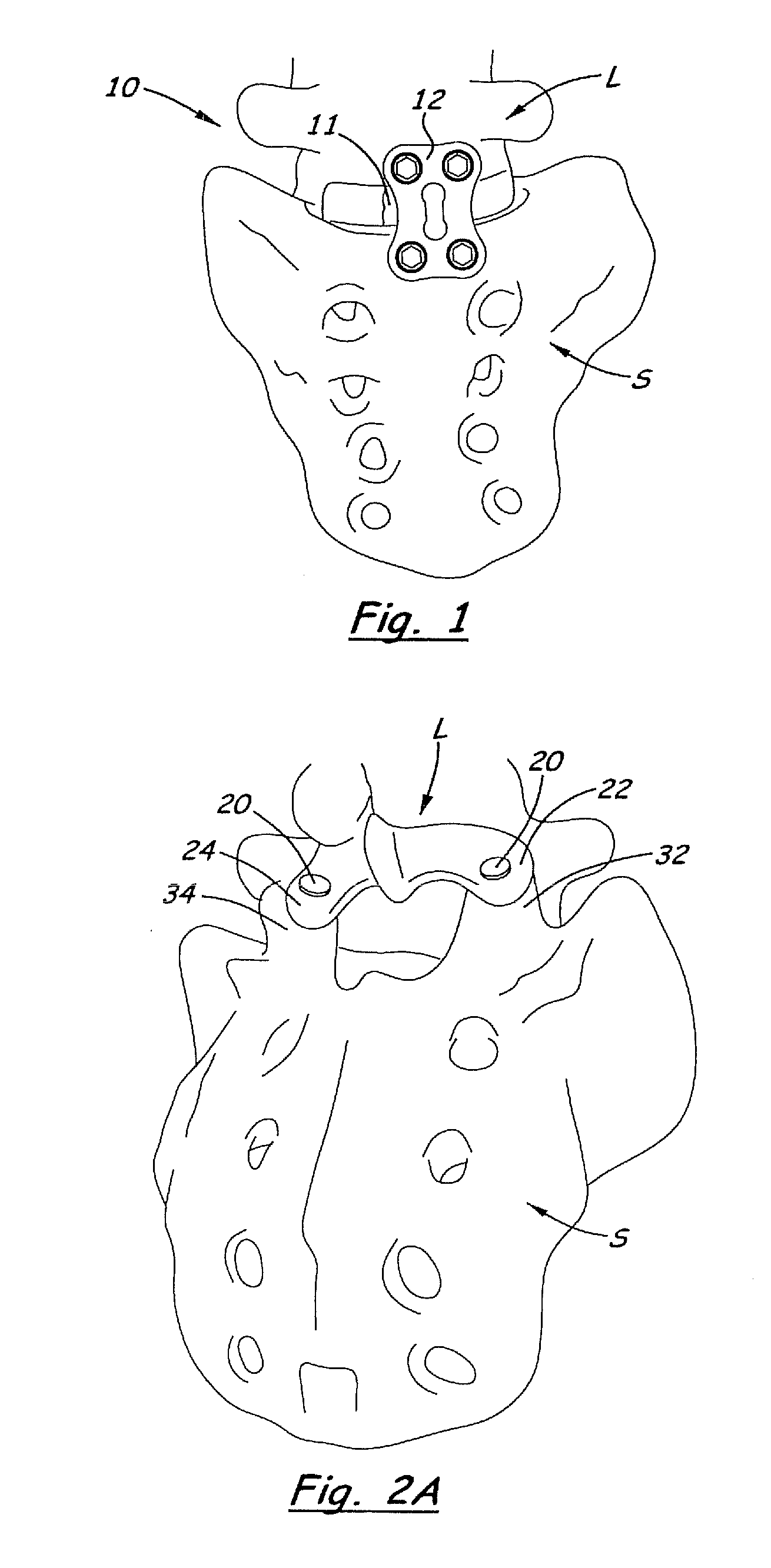
[0038]Preferably, the invented tacks are used in combination with an anterior fixation plate, such as that shown in FIG. 1. FIG. 1 is an anterior view of the lower lumbar region 10 of the spine, wherein one embodiment of an interbody implant 11 (preferably allograft), has been installed between the lowermost vertebra L and the sacrum S, and a fixation plate 12 has been installed on the anterior surfaces of said lowermost vertebra and sacrum. The rigid fixation plate 12 is screwed ...


PUM


Abstract

A tack for insertion into facets joints of the human spine includes one or more bioactive materials. The tack is preferably pushed / impacted axially into a hole in the facets, rather than rotated or screwed into the hole / facets. For example, the bioactive material may be outer sidewall(s) made of porous material that receives and / or encourages bone growth into its pores. Or, for example, the bioactive material may be osteobiologic material, demineralized bone matrix (DBM), sponge holding bone morphogenic protein (BMP), allograft bone, or other bioactive material inside an interior space of the tack. Apertures may be provided in the outer wall of a hollow tack to allow bone growth into the interior space of the tack. The tack may have a longitudinal passage, so that the tack may be installed on and slid along a guide-wire in percutaneous surgery that is guided by intraoperative imaging navigation. Preferably, the tack is not threaded, and is installed with little, and preferably no, rotation of the tack on its longitudinal axis.

Description

[0001]This application is a continuation-in-part of Non-Provisional application Ser. No. 12 / 541,912, filed Aug. 14, 2009, which claims benefit of Provisional Application Ser. No. 61 / 088,793, filed Aug. 14, 2008, Provisional Application Ser. No. 61 / 097,095, filed Sep. 15, 2008, and Provisional Application Ser. No. 61 / 161,074, filed Mar. 18, 2009, the entire disclosures of which provisional and non-provisional applications are incorporated herein by this reference.BACKGROUND OF THE INVENTION[0002]1. Field of the Invention[0003]The invention relates generally to apparatus for fixation of portions of the human spine, and, more particularly, to apparatus for fixing one vertebra to another, or a vertebra to the sacrum. The preferred apparatus is a tack, made from or comprising bioactive materials, which is axially inserted into holes in facets of said vertebra(e) and / or sacrum, rather than being screwed into said holes. Said preferred tack is surprisingly the only structure needed for pos...

Claims


Application Information

Patent Timeline
Patent Type & Authority Applications(United States)
IPC IPC(8): A61B17/88A61B17/86
CPCA61B17/0642A61B17/1757A61B17/1664A61B17/1671A61B17/7064A61B17/8625A61B17/8897A61B2017/00469A61B2017/00893A61B2017/0647A61B2019/5255A61L27/3608A61L31/005A61L2430/38A61B17/1615A61B2034/2055
Inventor DOERR, TIMOTHY E.
Owner DOERR TIMOTHY E
Learn More