Micromechanical Capacitive Sensor Element

a capacitive sensor and micro-mechanical technology, applied in the direction of instruments, semiconductor devices, measurement devices, etc., can solve problems such as the change of distan

Inactive Publication Date: 2011-05-12
ROBERT BOSCH GMBH
View PDF3 Cites 28 Cited by
  • Summary
  • Abstract
  • Description
  • Claims
  • Application Information

AI Technical Summary

Problems solved by technology

A pressure difference between the pressure prevailing in the cavity and the outside pressure results in bending of the diaphragm

Method used


Image

  • Micromechanical Capacitive Sensor Element
  • Micromechanical Capacitive Sensor Element
  • Micromechanical Capacitive Sensor Element

Examples


Embodiment Construction

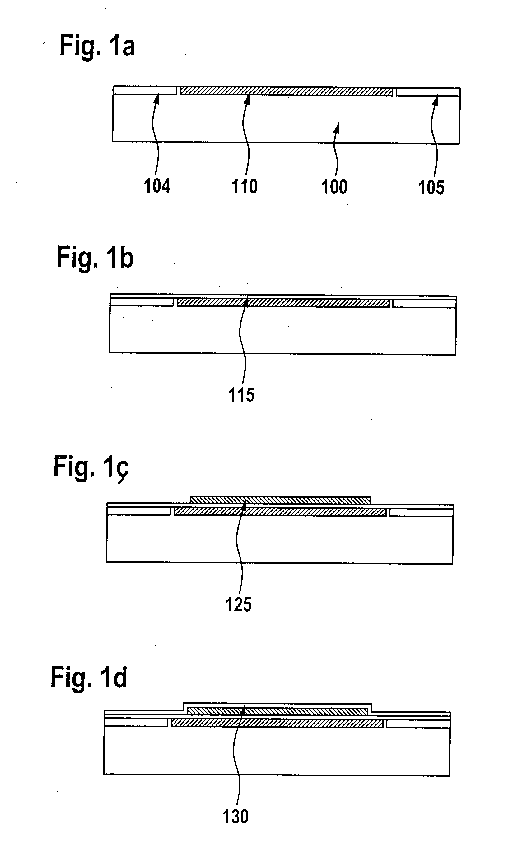
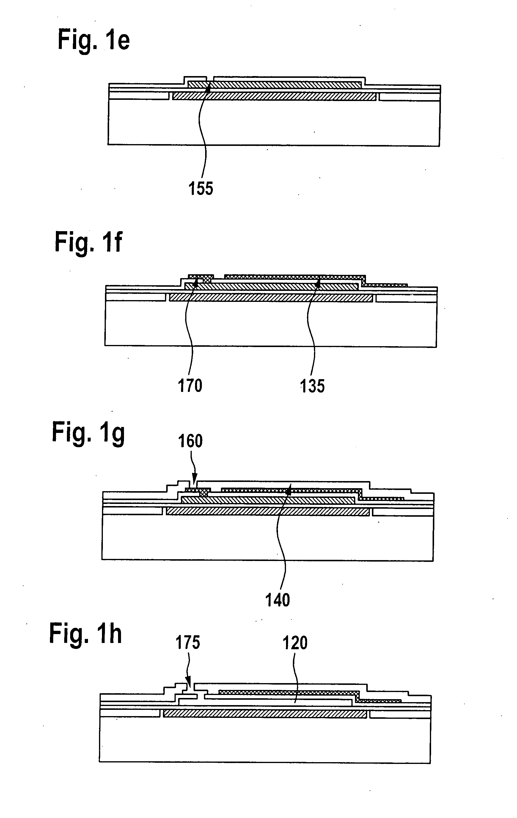
[0034]FIGS. 1a through k illustrate a possible manufacturing process for a monolithically integrated capacitive sensor element according to the present invention using micromechanical method steps. According to FIG. 1a, first electrode 110 is created in or on semiconductor substrate 100 by n-doping, for example. In addition, terminal regions 104 or insulation regions 105 may be created in or on semiconductor substrate 100. In other regions of the semiconductor substrate, gates may be formed using gate oxide, poly, etc.

[0035]FIG. 1b shows first layer 115 having a thickness of 40 nm to 250 nm applied to the entire circuit. The first layer is deposited at temperatures 110 and / or regions 104 and / or 105 from attack by ClF3, XeF2 or the like. First layer 115 is preferably made of oxide or nitride, but is preferably a TEOS layer applied to the surface at 400° C. with ozone support in a preferred thickness of 100 nm. When using thermal oxide (e.g., thick gate oxide) for first layer 115, 40 ...


PUM


Abstract

A manufacturing method for producing a micromechanical sensor element which may be produced in a monolithically integrable design and has capacitive detection of a physical quantity is described. In addition to the manufacturing method, a micromechanical device containing such. a sensor element, e.g., a pressure sensor or an acceleration sensor, is described.

Description

FIELD OF THE INVENTION[0001]The present invention is directed to the manufacture of a capacitive sensor element produced micromechanically in a monolithic design and a micromechanical device having such a sensor element, having at least one first electrode and one second electrode, a diaphragm and a cavity.BACKGROUND INFORMATION[0002]Capacitive surface micromechanical (SMM) pressure sensors are known in various embodiments. In contrast with piezoresistive sensors, capacitive sensors have the advantage that they are capable of analyzing the measuring capacitances contained therein using virtually no power. This is due mainly to the fact that they avoid the use of stress detectors in the form of piezoresistors through which high currents would otherwise flow. Furthermore, capacitive pressure sensors offer the advantage that they are largely independent of temperature.[0003]For many applications, it is desirable to have capacitive pressure sensors (or other capacitive sensor elements) ...

Claims


Application Information

Patent Timeline
IPC IPC(8): H01L29/84H01L21/02
CPCG01L9/0073
Inventor BENZEL, HUBERTFINKBEINER, STEFANFISCHER, FRANKBAUMANN, HELMUTMETZGER, LARSSCHEUERER, ROLANDBRAUCHLE, PETERFEUSTEL, ANDREASNEUBAUER, MATTHIAS
Owner ROBERT BOSCH GMBH
Why Eureka
Try Eureka