Electromechanical polarization switch

a polarization switch and electromechanical technology, applied in the field of antenna terminals, can solve the problems of high power performance, low loss, and increase the cost of the devi

Active Publication Date: 2011-05-12
VIASAT INC
View PDF24 Cites 19 Cited by
  • Summary
  • Abstract
  • Description
  • Claims
  • Application Information

AI Technical Summary

Benefits of technology

[0010]In an exemplary embodiment, this signal switching (and therefore this satellite capacity “load balancing”) can be performed periodically. In other exemplary embodiments, load balancing can be performed on many terminals (e.g., hundr

Problems solved by technology

A separate rotational actuator with independent control circuitry is generally required for each “baseball” switch 101, which increases the cost of device.
Th

Method used


Image

  • Electromechanical polarization switch
  • Electromechanical polarization switch
  • Electromechanical polarization switch

Examples


Embodiment Construction

[0022]While exemplary embodiments are described herein in sufficient detail to enable those skilled in the art to practice the invention, it should be understood that other embodiments may be realized and that logical electrical and mechanical changes may be made without departing from the spirit and scope of the invention. Thus, the following descriptions are not intended as a limitation on the use or applicability of the invention, but instead, are provided merely to enable a full and complete description of exemplary embodiments.

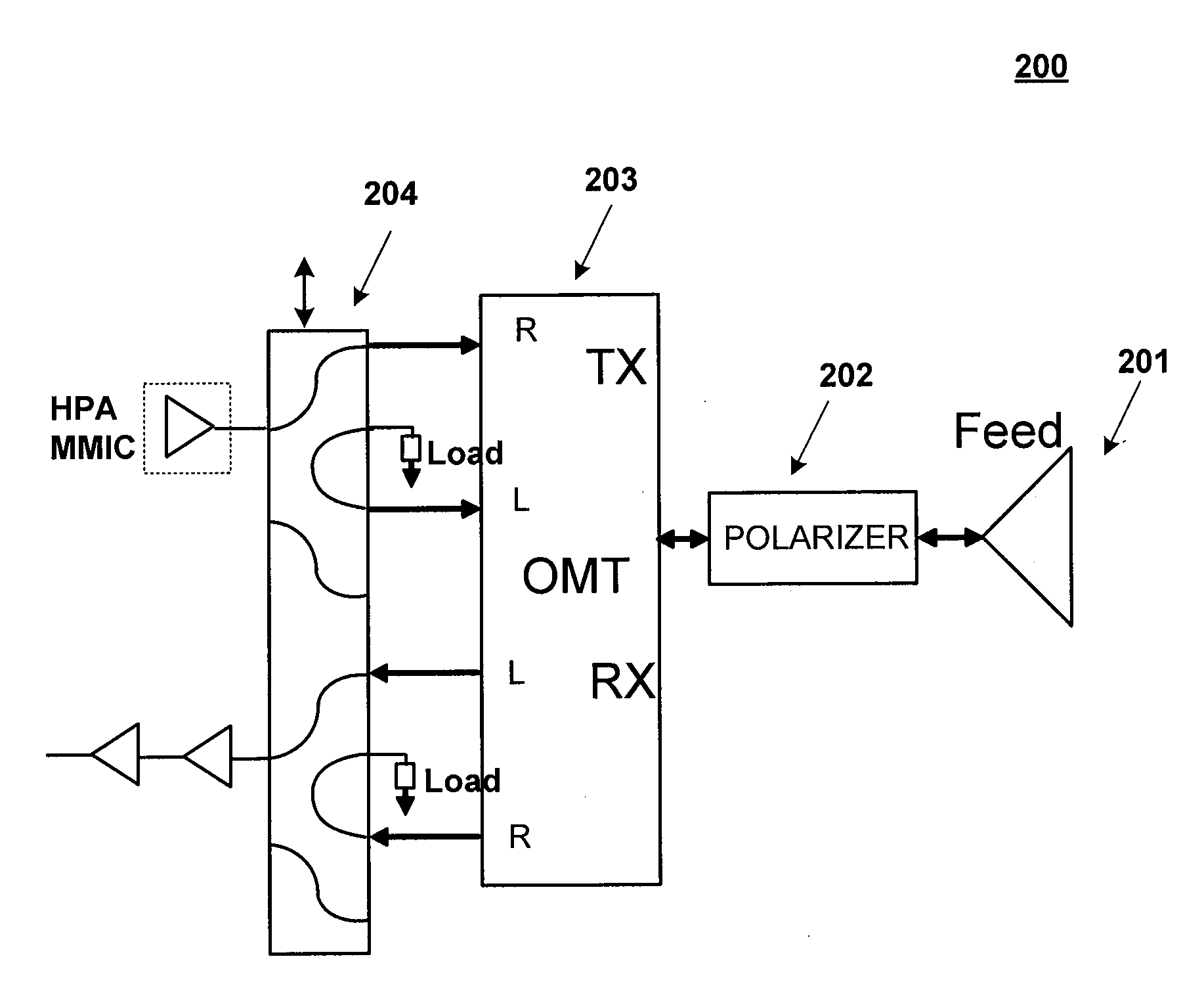
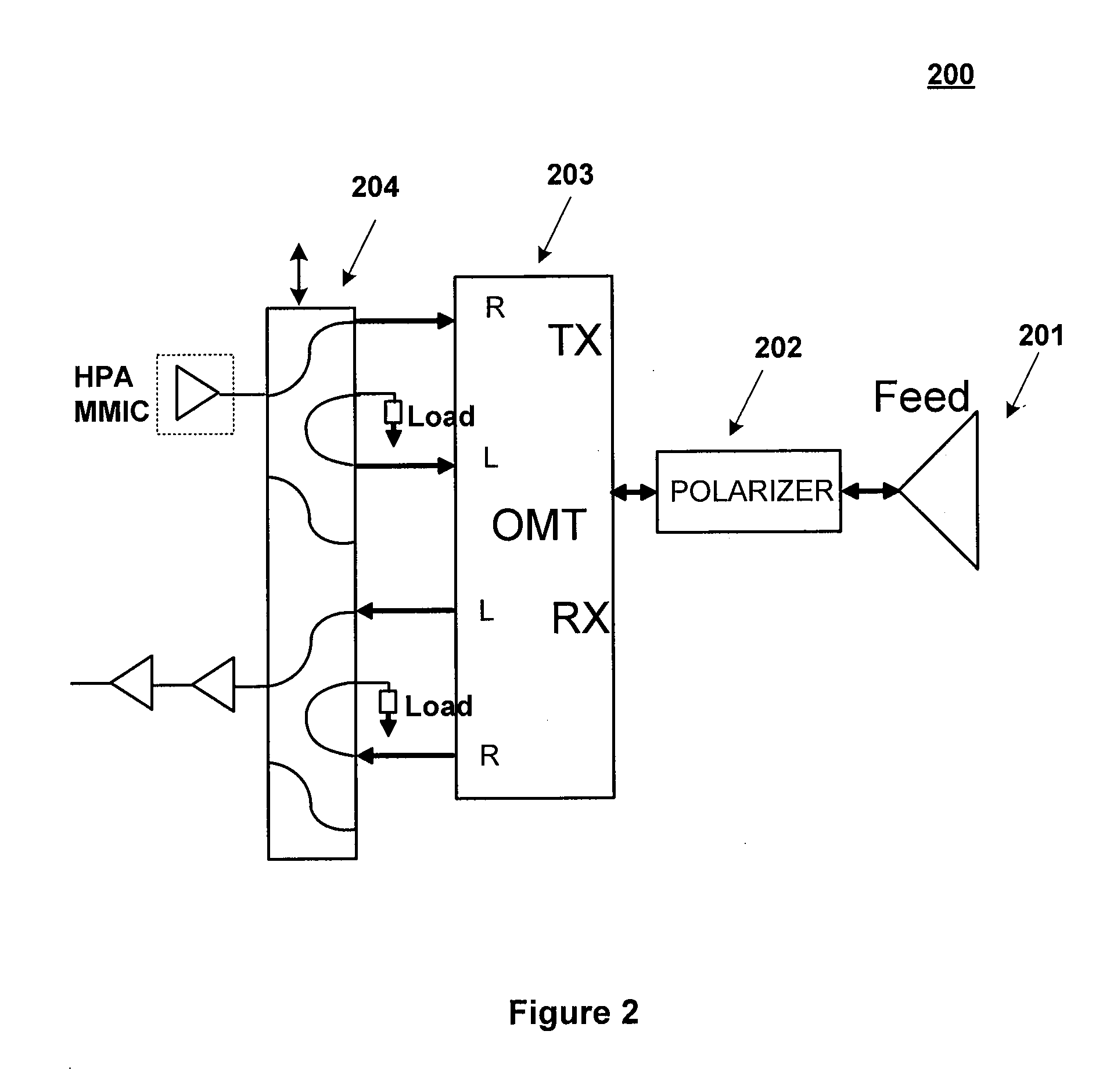
[0023]In accordance with an exemplary embodiment, polarization switching devices and methods are disclosed. The polarization switching may be done in conjunction with frequency switching, or it may be done while maintaining the same frequency. Thus, some discussion will follow regarding both polarization and frequency switching, but various embodiment switch only polarization. In an exemplary embodiment, an antenna transceiver is configured to change pola...


PUM


Abstract

In accordance with various aspects of the present invention, a method and system for electro-mechanical polarization switching in an antenna system is presented. The antenna system may comprise an integrated waveguide in a transceiver housing, where the waveguide has at least four channels. In an exemplary embodiment, a sliding switch is incorporated into the waveguide. The sliding switch is configured to switch the polarization of the antenna system by physically realigning the waveguide channels. The sliding switch may be electro-magnetically controlled. Furthermore, the polarization switching may be performed to assist in load balancing for a particular frequency and/or polarization combination.

Description

CROSS REFERENCE TO RELATED APPLICATIONS [0001]This application is a non-provisional of U.S. Provisional Application No. 61 / 259,053, entitled “ELECTROMECHANICAL POLARIZATION SWITCH,” which was filed on Nov. 6, 2009. This application is a non-provisional of U.S. Provisional Application No. 61 / 259,047, entitled “AUTOMATED BEAM PEAKING SATELLITE GROUND TERMINAL,” which was filed on Nov. 6, 2009. This application is a non-provisional of U.S. Provisional Application No. 61 / 259,049, entitled “DYNAMIC REAL-TIME POLARIZATION FOR ANTENNAS,” which was filed on Nov. 6, 2009. All of the contents of the previously identified applications are hereby incorporated by reference for any purpose in their entirety.FIELD OF THE INVENTION [0002]The subject of this disclosure may relate generally to systems, devices, and methods for an antenna terminal configured for polarization switching to increase system performance.BACKGROUND OF THE INVENTION[0003]A propagating radio frequency (RF) signal can have dif...

Claims


Application Information

Patent Timeline
IPC IPC(8): H01Q19/00
CPCH01P1/122H01Q25/00H01P1/161H01Q1/247
Inventor BUER, KENNETH V.TOR, JOSHLAIDIG, DAVID
Owner VIASAT INC
Why Eureka
Try Eureka