Eureka AIR delivers breakthrough ideas for toughest innovation challenges, trusted by R&D personnel around the world.

Inkjet head

Inactive Publication Date: 2011-05-12
SAMSUNG ELECTRO MECHANICS CO LTD +1
View PDF1 Cites 5 Cited by
  • Summary
  • Abstract
  • Description
  • Claims
  • Application Information

AI Technical Summary

Benefits of technology

[0010]An aspect of the present invention provides an inkjet head that efficiently supplies ink into a chamber to thereby improve printing quality.

Problems solved by technology

If the ink supply rate cannot catch up with the rate at which the ink is ejected, however, the ink is not ejected in midstream, thereby adversely affecting printing quality.

Method used


Image

  • Inkjet head
  • Inkjet head
  • Inkjet head

Examples


Embodiment Construction

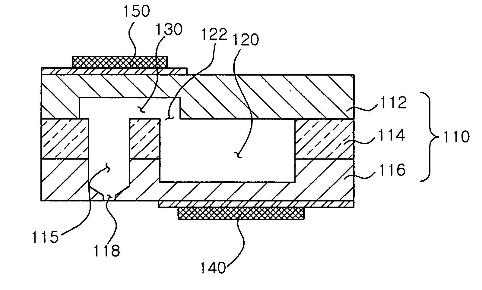
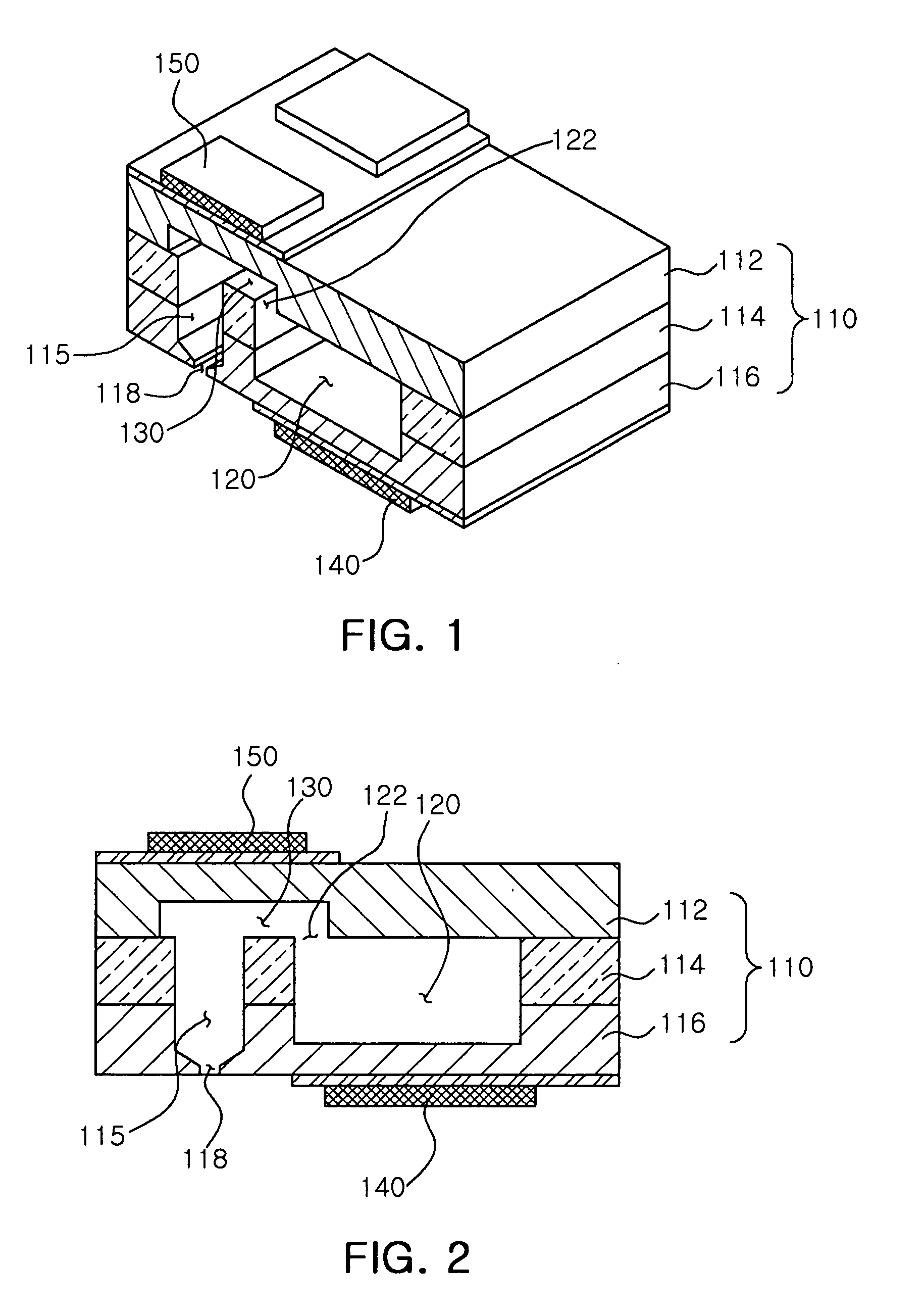
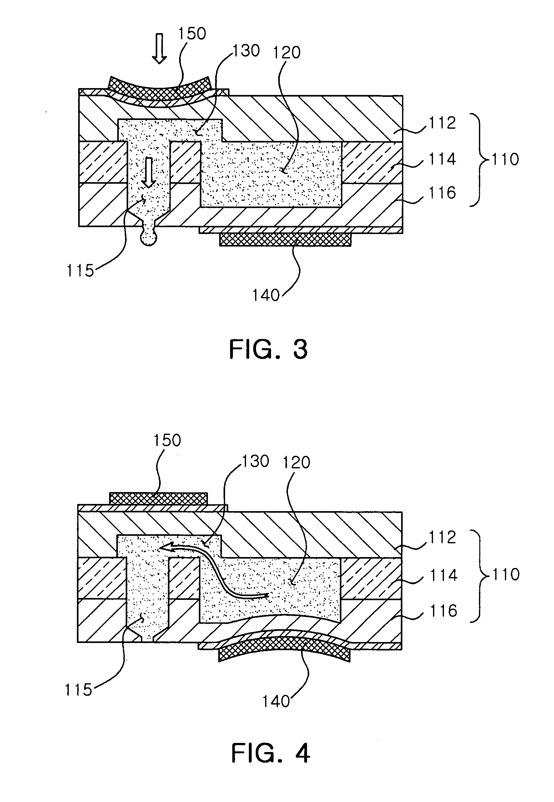
[0024]An inkjet head according to an exemplary embodiment of the invention will be described in more detail with reference to FIGS. 1 through 5. Exemplary embodiments of the present invention will now be described in detail with reference to the accompanying drawings.

[0025]The invention may, however, be embodied in many different forms and should not be construed as being limited to the embodiments set forth herein. While those skilled in the art could readily devise many other varied embodiments that incorporate the teachings of the present invention through the addition, modification or deletion of elements, such embodiments may fall within the scope of the present invention.

[0026]FIG. 1 is a schematic perspective view illustrating an inkjet head according to an exemplary embodiment of the invention. FIG. 2 is a cross-sectional view illustrating the inkjet head of FIG. 1.

[0027]Referring to FIGS. 1 and 2, an inkjet head may include a body 110, a reservoir 120, an ink chamber 130, a...


PUM


Abstract

There is provided an inkjet head. An inkjet head according to an aspect of the invention may include: a body having a nozzle in an outer surface thereof; a reservoir provided within the body and containing ink being externally injected; an ink chamber receiving the ink from the reservoir through a restrictor and ejecting the ink to an outside through the nozzle; and a reservoir actuator mounted on the body at a position corresponding to the reservoir and transmitting vibrations to the reservoir.

Description

CROSS-REFERENCE TO RELATED APPLICATIONS[0001]This application claims the priority of Korean Patent Application No. 10-2009-0107602 filed on Nov. 9, 2009, in the Korean Intellectual Property Office, the disclosure of which is incorporated herein by reference.BACKGROUND OF THE INVENTION[0002]1. Field of the Invention[0003]The present invention relates to inkjet heads, and more particularly, to a method of manufacturing an inkjet head that allows ink to be smoothly supplied to the inside of a chamber.[0004]2. Description of the Related Art[0005]In general, an inkjet head converts an electric signal into a physical force so that ink droplets are ejected through small nozzles.[0006]In recent years, piezoelectric inkjet heads have also been used in industrial inkjet printers. For example, a circuit pattern is directly formed by spraying ink prepared by melting metals such as gold or silver onto a printed circuit board (PCB). A piezoelectric inkjet head is also used for industrial graphics...

Claims


Application Information

Patent Timeline
IPC IPC(8): B41J2/045
CPCB41J2/055B41J2002/14419B41J2/14233B41J2/1433
Inventor KIM, JAE HUNJOUNG, JAE WOOKANG, YUN SUNGYANG, JU HWAN
Owner SAMSUNG ELECTRO MECHANICS CO LTD
Why Eureka
Eureka Blog
Learn More