Connector

a technology of connecting rods and connectors, applied in the direction of electrical apparatus, coupling device connections, printed circuits, etc., can solve the problems of user plugging the connector, the way of plugging the connector may be even unachievable, and the hardness of plugging/unplugging

Inactive Publication Date: 2011-05-12
AMTRAN TECH
View PDF37 Cites 5 Cited by
  • Summary
  • Abstract
  • Description
  • Claims
  • Application Information

AI Technical Summary

Problems solved by technology

Such receptacle connectors are primarily configured at the back or the side of a digital TV but getting much harder for plugging / unplugging since the digital TV is getting thinner with much little space left between the TV and the mounting wall.
Such short distance D stumbles plugging of the connector 4. FIG. 1 part A shows a common vertical mounting method of the connector 4, which is very difficult for a user to plug the connector 4. FIG. 1 part B shows a horizontal mounting method of the connector 4; however, such way of plugging the connector 4 may be even unachievable thanks to the limited space between the flat panel display 1 and the wall 2.
Besides the aforementioned A / V connectors, such as the D-sub, HDMI, DisplayPort, DVI connectors, used for a flat panel display, connectors applied on other types of devices, such as the network connectors, generic interfaces like USB, Firewire, may also face the same challenge because of the plugging angle.

Method used


Image

  • Connector
  • Connector
  • Connector

Examples


first embodiment

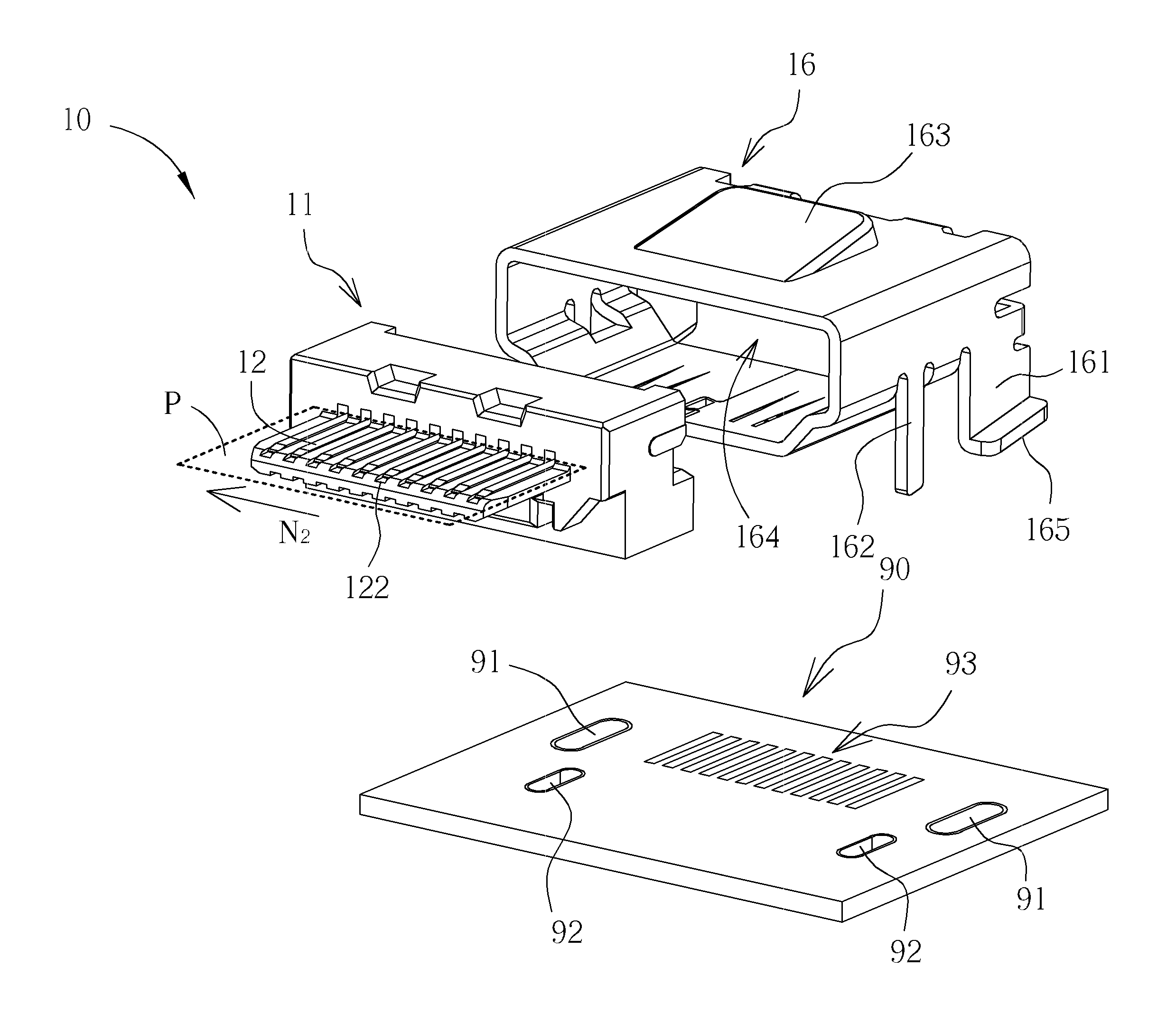
[0025]Please refer to FIG. 3 to FIG. 5, which are schematic diagrams showing an exemplary embodiment of a connector 10 according to the present invention. FIG. 3 shows the connector 10 and a corresponding circuit board 90 and FIG. 5 shows a side sectional view of the connector 10 mounted to the circuit board 90. The connector 10 according to the present invention includes a body 11 and a housing 16. The body 11 includes a plurality of signal pins 12, each having a first end 121 and a second end 122. The first ends 121 of the signal pins 12 electrically connect to electrical nodes 93 of the circuit board 90 while the second ends 122 of the signal pins 12 electrically connect to the electrical nodes of an external connector (not shown in the figure) when the external connector is plugged into the connector 10. In this embodiment, the first ends 121 of the signal pins 12 electrically connect to the electrical nodes 93 by means of surface mount device (SMD) technology. The body 11 and t...

second embodiment

[0030]Additionally, a plane surface 283 is further disposed at the top of the frame 28. The plane surface 283 is substantially parallel with the circuit board 80 and has similar function with the plane surface 163. In the second embodiment, the connector 20 is mounted to the circuit board 80 with the first ends 221 of the signal pins 22, the first feet 261 of the housing 26, and the second feet 281 of the frame 28, and is tilting with the circuit board 80 by use of the second feet 281 of the frame 28.

third embodiment

[0031]Please refer to FIG. 8 to FIG. 10, which are schematic diagrams showing a third exemplary embodiment of a connector 30 according to the present invention. FIG. 8 and FIG. 9 show the connector 30 mounted to a circuit board 70 shown in different angles and FIG. 10 shows a side sectional view of the connector 30 mounting to the circuit board 70. In the third embodiment, the connector 30 sinks in the circuit board 70 for decreasing the overall thickness. The circuit board 70 includes a breakup structure 74 and the connector 74 mounts to the circuit board 70 by using a pair of first feet 361 at both sides of the housing 36, where the first feet 361 have first inclined surfaces 365 for being attached to the circuit board 70 via SMD. The first ends 321 of the signal pins also electrically connect to the electrical nodes of the circuit board 70 via SMD. It is shown in FIG. 10 that part of the connector 30 sinks in the breakup structure 74 of the circuit board 70 when mounted therein a...


PUM


Abstract

A connector is mounted on a circuit board via its feet of the housing (and/or a frame's feet) mounted at a tilting angle to the circuit board, or via a wedge base of its connector body such that the signal pins and the opening of the housing extend along a direction at the tilting angle relative to the circuit board. An external connector may be plugged into the tilting-type connector at a tilting angle. The feet and signal pins of the connector may be mounted to the circuit board by use of surface mount device (SMD) technology or direct insertion. A plane may be further deployed on the top of the connector for being used by an SMD equipment.

Description

BACKGROUND OF THE INVENTION[0001]1. Field of the Invention[0002]The invention relates to a connector, and more particularly, to a connector having tilting mounting angle with respect to a PCB.[0003]2. Description of the Prior Art[0004]Digital TV has the trend of getting thinner and incorporating with wall-mount structure so as to blend into housing design. With multiple fields' application and higher supportability in A / V, communications, data processing designed for the TV, receptacle connectors for various external connectors are also enhanced. Such receptacle connectors are primarily configured at the back or the side of a digital TV but getting much harder for plugging / unplugging since the digital TV is getting thinner with much little space left between the TV and the mounting wall.[0005]Please refer to FIG. 1, which is a schematic diagram of a conventional flat panel display 1 showing the situations of its connector 4 when the flat panel display 1 is mounted to the wall 2. The...

Claims


Application Information

Patent Timeline
Patent Type & Authority Applications(United States)
IPC IPC(8): H01R12/16
CPCH01R13/6581H01R12/724
Inventor CHEN, MIN-IHO, YUNG-HUNGHSU, WEI-CHIEH
Owner AMTRAN TECH
Why Eureka
Try Eureka