Devices, systems and methods for meniscus repair

a meniscus and system technology, applied in the field of meniscus repair devices, can solve the problems of damage to the surrounding articular cartilage, pain and loss of joint function, and early arthritis, and achieve the effect of preventing tissue damage and preventing tissue damag

Active Publication Date: 2011-05-12
CETERIX ORTHOPAEDICS
View PDF99 Cites 31 Cited by
  • Summary
  • Abstract
  • Description
  • Claims
  • Application Information

AI Technical Summary

Benefits of technology

[0012]In general, the meniscus repair suture passer devices described herein are configured as continuous suture passers that may pass a suture back and forth between two arms or jaw between which the tissue (e.g., meniscus or adjacent tissues) is positioned. A meniscus repair suture passer may include a first arm (which may also be referred to as a lower arm) that is axially slideable relative to a second arm (which may also be referred to as an upper arm). The device may also include a tissue penetrator that extends between the arms, preferably in a curved or arcuate path. The tissue penetrator may alternately (cyclically) secure and release a suture (e.g., using a suture shuttle to which a suture may be connected), allowing the tissue penetrator to pull and push the suture shuttle between the first and second arm in cycles that alternate with leaving the suture shuttle (or, in some variations, the suture itself) in a dock, e.g., shuttle dock, on the arm that is opposite from the arm into which the tissue penetrator retracts into. These features may allow the meniscus repair suture passer to continuously pass a suture back and forth through a tissue without requiring that the suturing device be removed from the knee, or even removed off of the meniscus.
[0020]In general, when the first arm, which is typically “straight” or extending in the same direction as the long axis of the device, is retracted proximally, the lower “arm” of the distal opening is missing, so the device has just a narrow, bent, distal end formed by the distal end region of the second arm. This distal end region may be used to position the device within the knee near the meniscus. The small size and dimensions of the distal end when the first arm is retracted proximally (completely) may allow the device to navigate the tissue of the knee without undue damage to other tissues. Extending the first (lower) arm distally may form the “v-shape” mentioned above. In general, the tips of the distal ends of the second and first arms are rounded and atraumatic. In particular, the tips may be blunt to prevent damage to tissue as the device is positioned.
[0021]In some variations, the tissue penetrator is configured to be housed within the distal end of the first arm. The tissue penetrator may be completely retracted into the first arm, which may prevent damage to tissue as the device is maneuvered into position around the meniscus. In some variations, the tissue penetrator is configured to extend from the second, rather than the first arm, in which case the configuration of the tissue penetrator and dock (e.g., shuttle dock) may be reversed.

Problems solved by technology

Typically, when the meniscus is damaged, the torn piece begins to move in an abnormal fashion inside the joint, which may lead to pain and loss of function of the joint.
Early arthritis can also occur due to these tears as abnormal mechanical movement of torn meniscal tissue and the loss of the shock absorbing properties of the meniscus commonly lead to destruction of the surrounding articular cartilage.
While this may be done arthroscopically, surgical repair using a suture may be difficult because of the difficult-to-reach nature of the procedure and the difficulty in placing sutures in a way to compresses and secures the torn surfaces.
Most prior art devices for suturing or repairing the meniscus are only capable of reliably repairing vertical / longitudinal tears.
In FIGS. 6A-6C the devices affecting these repairs require projection through the meniscus and substantially into the capsule region outside of the meniscus, which could potentially damage the nearby major nerves and large blood vessels.
Further, the prior art devices, such as those placing the sutures illustrated in FIG. 6A-6C, typically place horizontal mattress suture patterns rather than vertical mattress suture patterns because vertical patterns are considerably more difficult for surgeons to place when using these devices.
Additionally, the devices forming the suture patterns illustrated in FIG. 6A-6C are only capable of point fixation; that is they cannot compress the tears uniformly across the torn surface.
Finally, such prior art devices are designed for repairing peripheral vertical meniscus tears (torn from the superior surface to the inferior surface in line with the C-shape of the meniscus) and are incapable of repairing commonly encountered radial meniscus tears.

Method used


Image

  • Devices, systems and methods for meniscus repair
  • Devices, systems and methods for meniscus repair
  • Devices, systems and methods for meniscus repair

Examples


Embodiment Construction

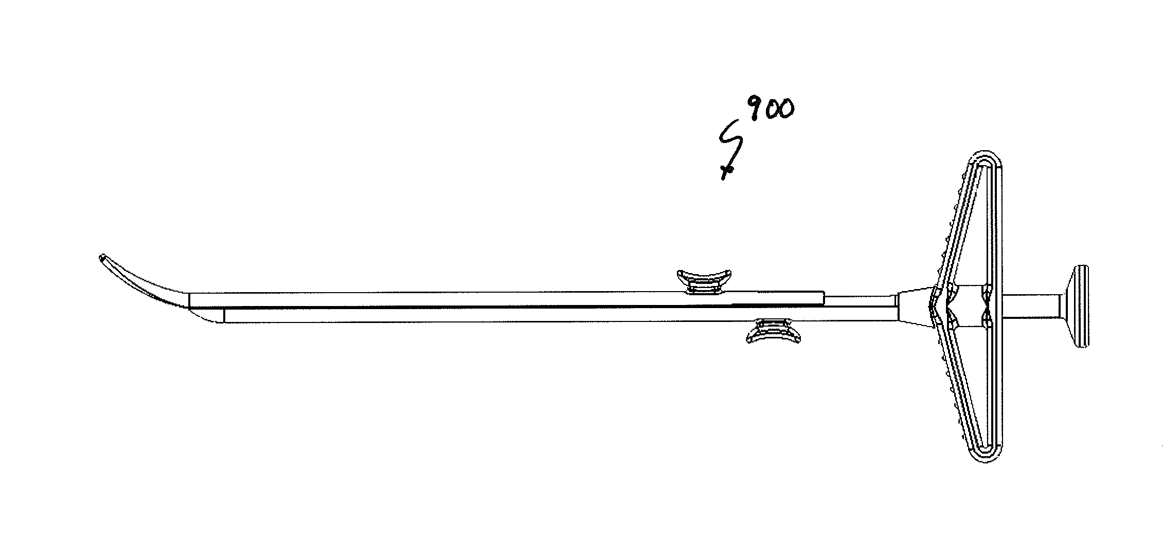
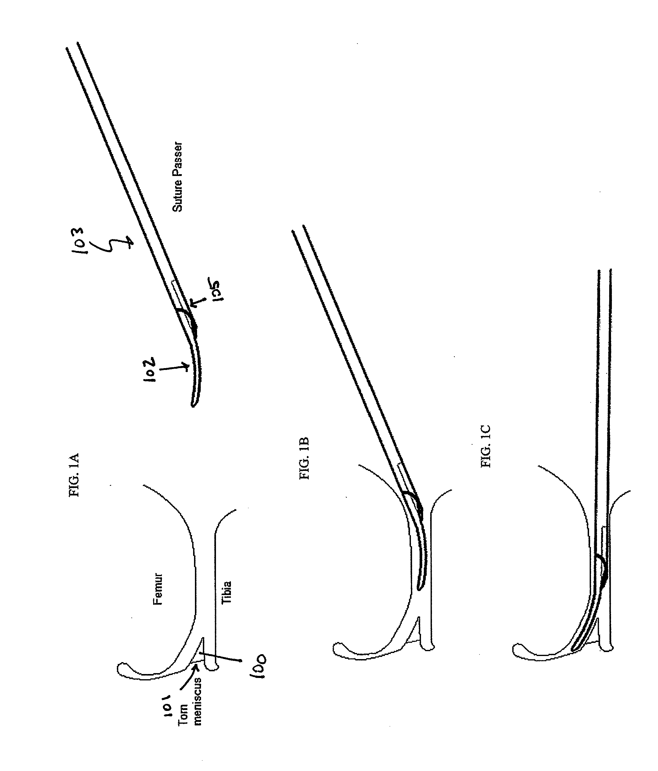
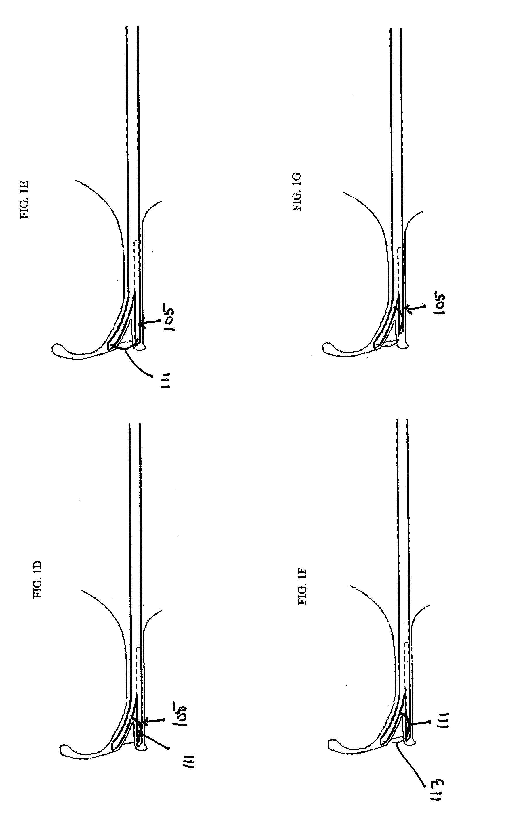
[0080]Described herein are suture passers for meniscus repair. In general, these devices may be referred to herein as meniscus repair suture passers, meniscus repair devices, or simply suture passers. The devices described herein may be configured to repair a meniscus (knee joint meniscus), and may have two arms which extend longitudinally and can be expanded around a meniscus from a lateral (central) approach. Typically, the distal end region (e.g., the distal-most 3 or less cm) of one of the arms is bent or bendable at an angle away from the long axis of the device, and the other arm is axially movable distally and proximally (in the direction of the long axis of the device). Extending the distally and proximally movable arm distally will form an acute angled opening at the distal end that can be positioned around the meniscus, and a suture can be passed from one arm to the other through the meniscus or adjacent tissues to repair meniscal tears. The suture may be passed back and f...


PUM


Abstract

Described herein are meniscus suture passers for repair of the meniscus of the knee. These devices are typically continuous suture passers that may include an elongate body having a pair of arms. One or more of the arms may be angled or bent at the distal end region relative to the long axis of the device, forming a distal-facing opening that is configured to fit meniscus tissue. One or both arms may be movable in the axial direction (e.g., the direction of the long axis of the device). The devices typically include a tissue penetrating element housed within one of the arms but configured to extend across the distal opening between and communicate with one or more docking regions on the opposite arm to alternately retain and release a suture (or a suture connected to a suture shuttle). Thus, a suture may be passed from a first side of the tissue to a second side and back to the first side multiple times.

Description

CROSS REFERENCE TO RELATED APPLICATIONS[0001]This patent application claims priority to U.S. Provisional Patent Applications: Ser. No. 61 / 259,572, titled “DEVICES, SYSTEMS AND METHODS FOR MENISCUS REPAIR” filed Nov. 9, 2009; Ser. No. 61 / 295,354, titled “DEVICES, SYSTEMS AND METHODS FOR MENISCUS REPAIR” and filed on Jan. 15, 2010; and Ser. No. 61 / 318,215, titled “CONTINUOUS SUTURE PASSERS HAVING TISSUE PENETRATING SUTURE SHUTTLES” filed on Mar. 26, 2010. All of these applications are herein incorporated by reference in their entirety.[0002]This application may also be related to U.S. patent application Ser. No. 11 / 773,388, titled “METHODS AND DEVICES FOR CONTINUOUS SUTURE PASSING,” and filed on Jul. 3, 2007; and U.S. patent application Ser. No. 12 / 291,159, titled “SUTURE PASSING INSTRUMENT AND METHOD,” filed on Nov. 5, 2008. Both of these applications are herein incorporated by reference in their entirety.INCORPORATION BY REFERENCE[0003]All publications and patent applications mentio...

Claims


Application Information

Patent Timeline
Patent Type & Authority Applications(United States)
IPC IPC(8): A61B17/04
CPCA61B17/0469A61B17/0482A61B17/062A61B17/88A61B2017/06009A61B2017/06042A61B2017/0496
Inventor SALIMAN, JUSTIN D.JASSO, ALEXANDERANASTAS, GEORGE V.
Owner CETERIX ORTHOPAEDICS
Why Eureka
Try Eureka