Disposition zone in an aircraft passenger cabin

a technology for disposing zones and passenger cabins, which is applied in the field of disposing zones in aircraft passenger cabins, can solve the problems of reducing the passenger space of the module, affecting the service life of passengers, and affecting the work efficiency of passengers in business class, so as to improve the services and comfort offered to passengers

a technology for disposing zones and passenger cabins, which is applied in the field of disposing zones in aircraft passenger cabins, can solve the problems of reducing the passenger space of the module, affecting the service life of passengers, and affecting the work efficiency of passengers in business class, so as to improve the services and comfort offered to passengers

US20110114788A1Active Publication Date: 2011-05-19AIRBUS OPERATIONS GMBH

Image

  • Disposition zone in an aircraft passenger cabin
  • Disposition zone in an aircraft passenger cabin
  • Disposition zone in an aircraft passenger cabin

Examples


Embodiment Construction

[0048]In the description of FIGS. 1 to 11d, analogous or corresponding components and elements are at least in part identified by the same reference symbols. Furthermore, the uniform term space unit is used for the door entry area and door exit area of the passenger cabin.

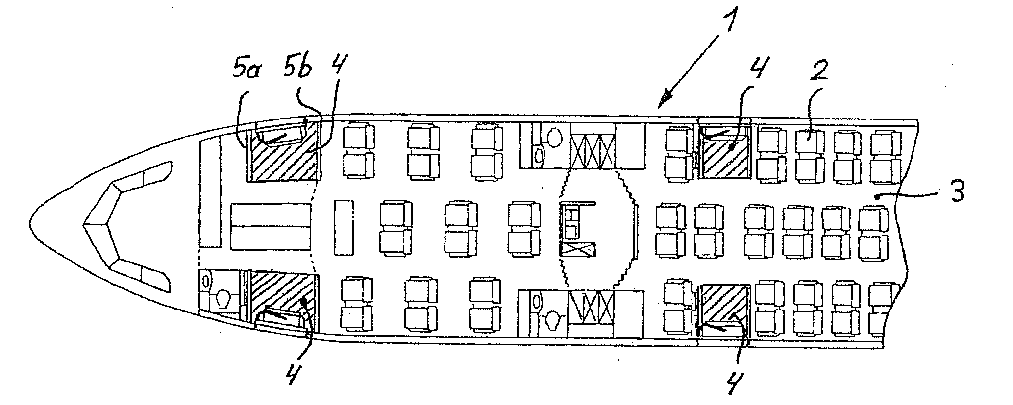
[0049]FIG. 1 shows the design of a section of an aircraft 1 in the form of a sectional representation and elucidates the seat layout of passenger seats 2 in a passenger cabin 3, as well as the arrangement or distribution of the door entry and door exit areas that are referred to as space units 4 and respectively illustrated in a hatched fashion. According to the invention, the space units 4 form disposition zones that can be used for different service and / or comfort facilities and also referred to as Working Areas. In this case, the space units 4 are laterally bounded by partition walls 5a, 5b that extend from a cabin floor up to a cabin ceiling.

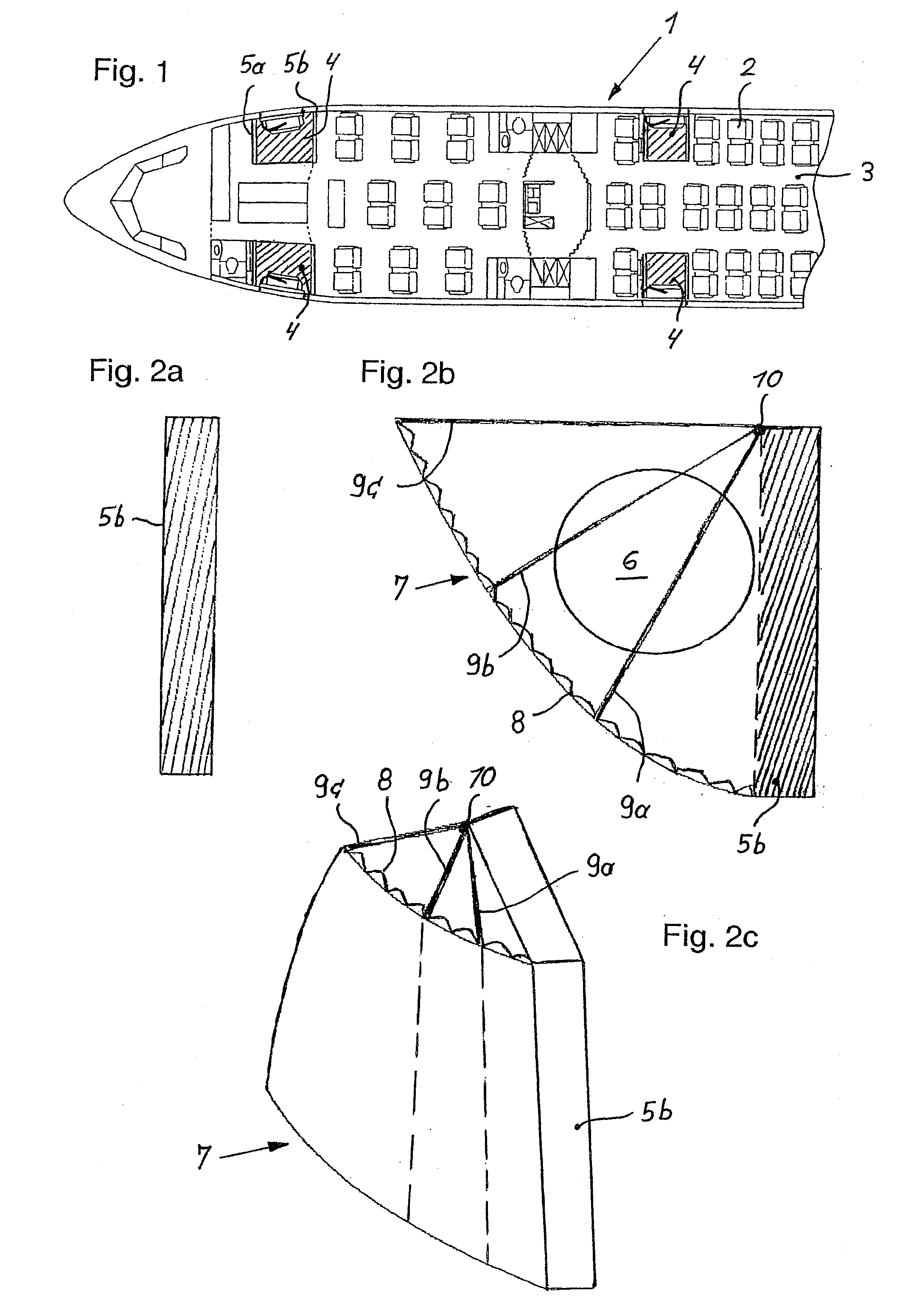
[0050]FIGS. 2a to 2c show the design and the arrangement of a calling ...


PUM


Abstract

The invention pertains to an aircraft with at least one passenger cabin that comprises at least one door entry area for the passengers and for the flight attendants that is visually separated from the passenger cabin and referred to as a space unit. Variable or mobile elements assigned to at least one partition wall / one monument of the space element can be arranged in the space unit that can be used as a disposition zone during the flight phase in order to realize working areas or service and / or comfort facilities for passengers or for the flight attendants.

Description

FIELD OF THE INVENTION[0001]The invention pertains to an aircraft with at least one passenger cabin comprising at least one door entry area or door exit area for the passengers and for the flight attendants that is visually separated from the passenger cabin and referred to as a space unit.TECHNOLOGICAL BACKGROUND[0002]In order to meet the requirements in the context of new developments of aircraft and the demands in the near future, it is necessary to improve the service and the comfort and to equip aircraft, for example, with Working Areas.[0003]DE 43 01 681 C1 discloses a service unit in the form of a so-called PSU module (Passenger Service Unit) for aircraft, in which, for example, reading lamps, information signs, loudspeakers, seat row numbering, optical safety information and an attendant call button (Attendant Call Button) are combined. These PSU are usually arranged above the rows of passenger seats. DE 199 26 782 A1 pertains to a service unit that is positioned on a side w...

Claims


Application Information

Patent Timeline
19 May 2011
Publication
US20110114788A1
IPC
B64D11/00
CPC
B64D11/0023
Inventors
MOSLER, MICHAEL; ULBRICH-GASPAREVIC, JOVAN