Systems and methods for electronically controlling the viewing angle of a display

Active Publication Date: 2011-05-19
APPLE INC
View PDF12 Cites 19 Cited by
  • Summary
  • Abstract
  • Description
  • Claims
  • Application Information

AI Technical Summary

Benefits of technology

[0004]For example, in some embodiments, there is provided an electronic device that may include a housing having an opening through a portion of the housing, a light source that directs light towards the opening, and a first display control subassembly. The first display control subassembly may include a scattering module positioned between the light source and the opening. The scattering module may include a plurality of scattering regions. The first display control subassembly may also include a steering module positioned between the light source and the scattering module. The steering module may include a liquid crystal material that is electronically controllable to direct a light beam from the light source towards a particular scattering region of the plurality of scattering regions.
[0005]The plurality of scattering regions may include a first scattering region that scatters light from the steering module towards the opening with a first viewing angle with respect to a first axis, and a second scattering region that scatters light from the steering module towards the opening with a second viewing angle with respect to the first axis. The second viewing angle may be different than the first viewing angle. In some embodiments, the steering module may include a linear electric field gradient across the liquid crystal material. In other embodiments, the

Problems solved by technology

However, due to processing limitations, display limitations, size limitations, and other limitations of such electronic devices, a u

Method used


Image

  • Systems and methods for electronically controlling the viewing angle of a display
  • Systems and methods for electronically controlling the viewing angle of a display
  • Systems and methods for electronically controlling the viewing angle of a display

Examples


Embodiment Construction

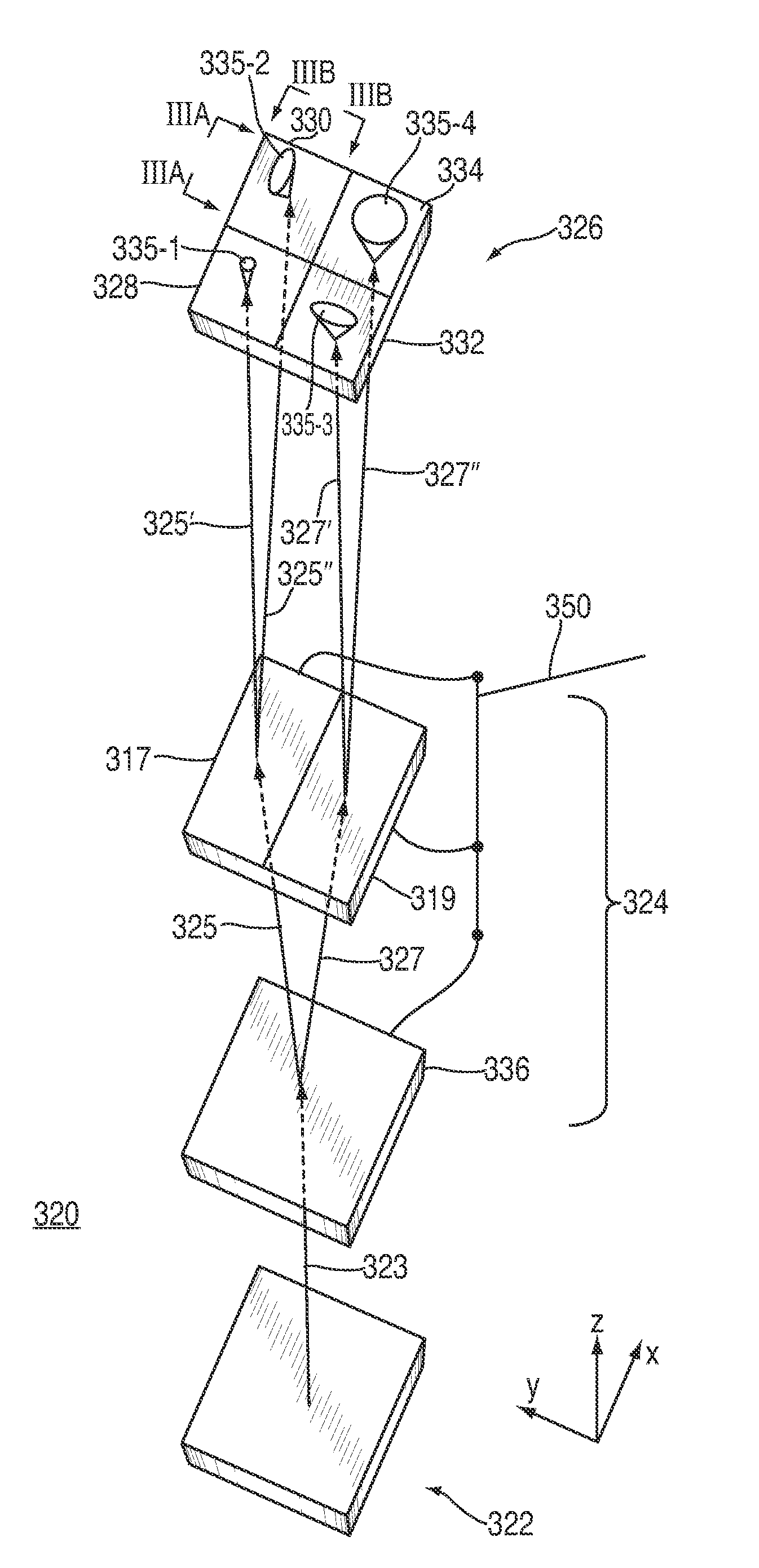
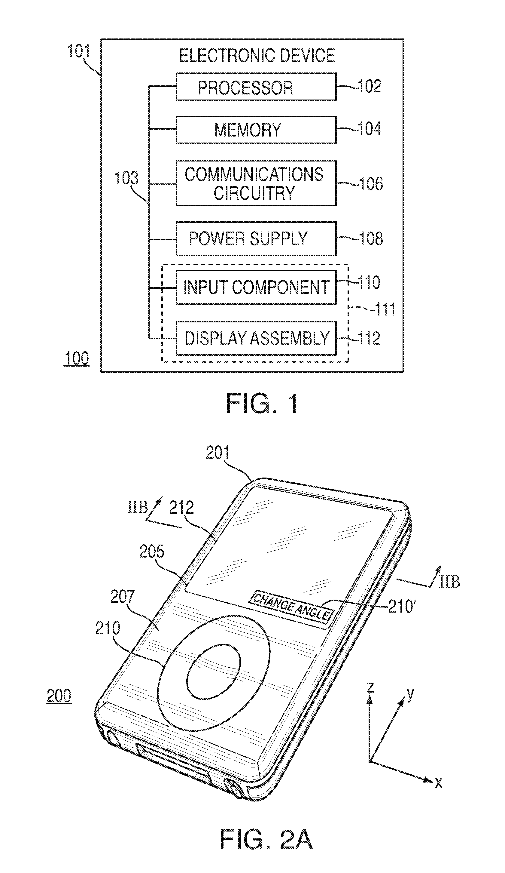
[0020]Systems and methods for electronically controlling the viewing angle of a display screen are provided and described with reference to FIGS. 1-6.

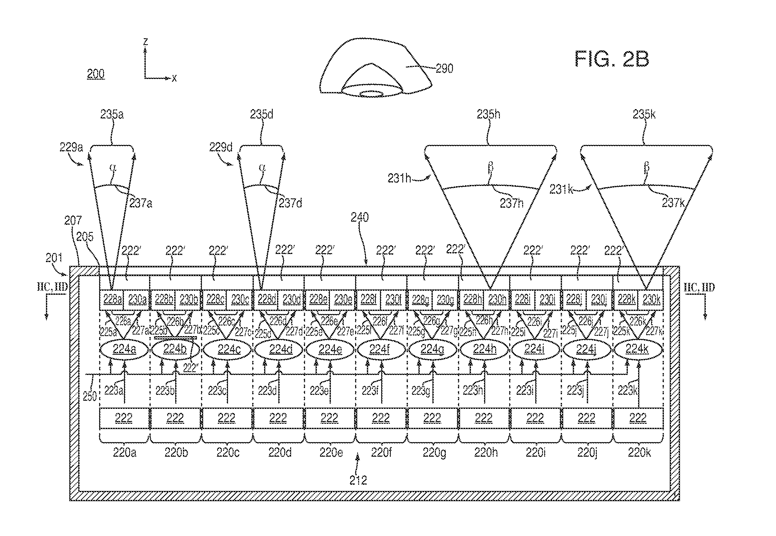
[0021]An electronic device may be operative to provide visible information to a user. For example, an electronic device may include a display assembly operative to present the visible information at various viewing angles. The display may be provided with one or more steering modules, each of which may be associated with a respective scattering module having two or more scattering regions. Each steering module may selectively steer a device generated light beam to one of the scattering regions of its associated scattering module. When a scattering region receives a steered light beam, the steered light beam may be scattered into a viewing cone having at least one viewing angle that may be at least partially defined by a characteristic of that scattering region. Therefore, the particular scattering region of a scattering module towards ...


PUM


Abstract

Systems and methods for electronically controlling the viewing angle of a display using liquid crystal optical elements are provided. Each liquid crystal optical element may be associated with a respective scattering module and may selectively steer a device generated light beam to one of two or more scattering regions of its associated scattering module. When a scattering region receives a steered light beam, the steered light beam may be scattered into a viewing cone having at least one viewing angle defined by a characteristic of that scatter region. Each liquid crystal optical element may be made from one or more suitable liquid crystal materials that can be controlled electronically to vary the effective index of refraction of one or more different regions of the liquid crystal optical element, thereby steering incoming light towards a particular one of two or more scattering regions of an associated scattering module.

Description

FIELD OF THE INVENTION[0001]This can relate to systems and methods for controlling the viewing angle of a display and, more particularly, to systems and methods for electronically controlling the viewing angle of a display using liquid crystal optical elements.BACKGROUND OF THE DISCLOSURE [0002]Many electronic devices include the ability to present visible information to a user. In particular, many cellular telephones, laptop computers, and other portable electronic devices include a display screen for projecting light beams representative of device generated information to one or more viewers. Often, a user of the device may choose to share this displayed information with others looking at the device from various angles with respect to the screen, while, in other situations, the user may only want a person positioned directly in front of the screen to be able to see the displayed information. However, due to processing limitations, display limitations, size limitations, and other l...

Claims


Application Information

Patent Timeline
IPC IPC(8): G02F1/133G02F1/1335
CPCG02F1/1323G02F1/292G02F1/133504G02F1/137
Inventor GERE, DAVID S.
Owner APPLE INC
Why Eureka
Try Eureka