Immobilization device

Active Publication Date: 2011-05-19
OSSUR HF
View PDF56 Cites 3 Cited by
  • Summary
  • Abstract
  • Description
  • Claims
  • Application Information

AI Technical Summary

Benefits of technology

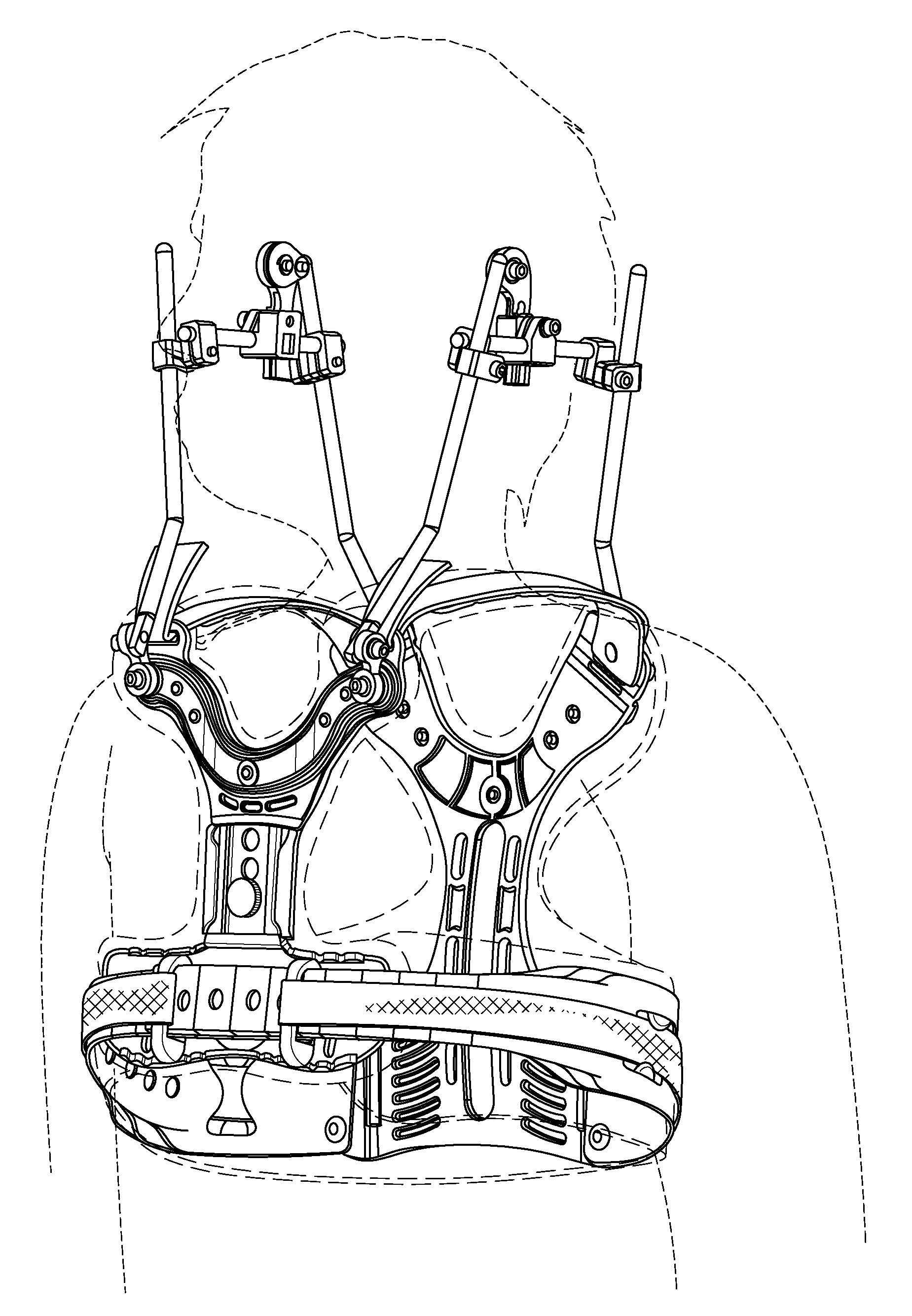
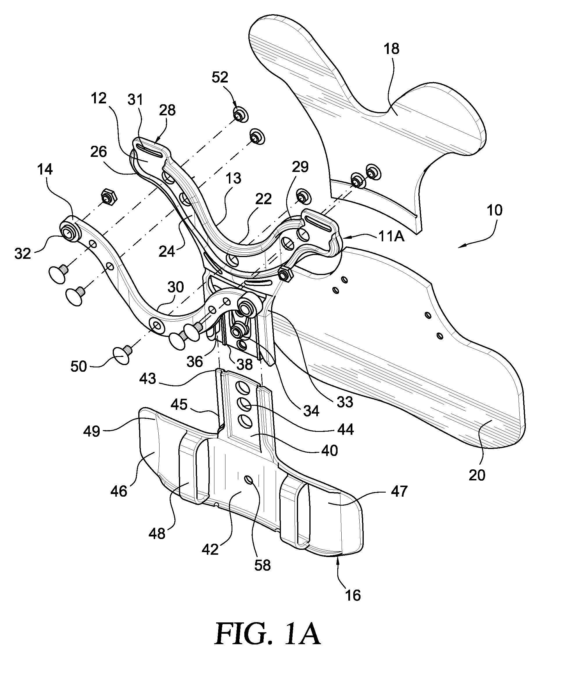
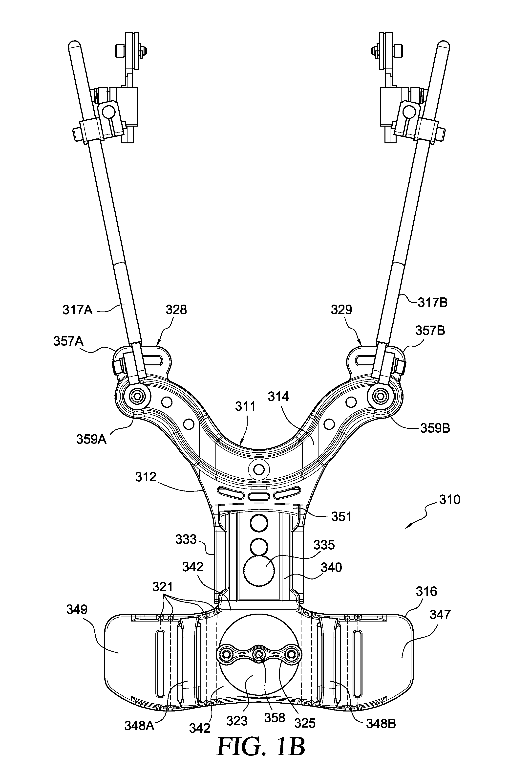
[0018]In another embodiment of the immobilization device, an anterior component defines portions contoured to a shape of a human chest. The anterior component has a bottom portion defining a central lower region including first and second opposed sides forming first and second belt loops, respectively, protruding outwardly from the bottom portion. First and second wings extend from beyond the corresponding first and second belt loops. The central lower region forms first and second living hinges located near the corresponding first and second belt loops, and the hinges are biased so as to facilitate drawing the first and second opposed sides of the central lower portion inwardly toward one another and against a wearer's abdominal region. It will be understood that this arrangement allows for a more secure fit over the wearer's abdominal or lower chest regions and more effectively distributes pressure exerted on the wearer by the lower strapping system.
[0020]According to another embodiment, the immobilization device has an anterior component including a two-dimensional shaped section contoured to a shape of the human chest. The anterior component forms an anterior outwardly bowed area relative to the two-dimensional shaped anterior section and corresponds to the sternum of the wearer. The anterior component includes a top component, and a bottom component having a central strut segment extending in a substantially vertical configuration. The top component has a substantially vertical attachment portion slidably engaging the bottom component. The top component defines an upper portion extending inwardly at a transition point toward a wearer at an oblique angle relative to the attachment portion. This arrangement permits the top component to more closely conform to the anatomy of the wearer.

Problems solved by technology

While there are numerous known immobilization devices, many of these known devices are inadequate at comfortably distributing pressure exerted onto the chest of the wearer from the halo upright assembly.
In particular, many conventional devices apply pressure to anatomical regions that are sensitive to loading.
These known devices are cumbersome to apply, particularly for weakened wearers, and do not adequately adapt to the anatomy of the wearer.
Moreover, known devices are often found to be ill fitting and lack means for adjustment to a variety of anatomical sizes.

Method used


Image

  • Immobilization device
  • Immobilization device
  • Immobilization device

Examples


Embodiment Construction

[0036]A. Overview

[0037]A better understanding of different embodiments of the invention may be had from the following description read in conjunction with the accompanying drawings in which like reference characters refer to like elements.

[0038]While the disclosure is susceptible to various modifications and alternative constructions, certain illustrative embodiments are shown in the drawings and are described below in detail. It should be understood, however, that there is no intention to limit the disclosure to the specific embodiments disclosed, but on the contrary, the intention is to cover all modifications, alternative constructions, combinations, and equivalents falling within the spirit and scope of the disclosure.

[0039]It will be understood that, unless a term is expressly defined in this patent to possess a described meaning, there is no intent to limit the meaning of such term, either expressly or indirectly, beyond its plain or ordinary meaning

[0040]Any element in a clai...


PUM


Abstract

An immobilization device including an anterior component including a two-dimensional shaped section contoured to a shape of the human chest and an anterior outwardly bowed area relative to the two-dimensional shaped anterior section generally corresponding to the sternum of the wearer. The device also includes a posterior component including a two-dimensional shaped section contoured to a shape of the human back and a posterior outwardly bowed area relative to the two-dimensional shaped section corresponding to the spinal column of the wearer, with elongate cushion elements connected to and extending within a width of the posterior outwardly bowed area. A strapping system connects both the anterior and posterior components to one another.

Description

CROSS-REFERENCE TO RELATED APPLICATIONS[0001]This application is a continuation-in-part of U.S. application Ser. No. 12 / 617,819, filed on Nov. 13, 2009, the entirety of which is incorporated herein by reference.FIELD OF THE INVENTION[0002]The present invention relates to an immobilization device for use by wearers having cervical or spinal injuries. Specifically, the immobilization device functions to fully or partially immobilize the head and neck of the wearer by way of vest components for supporting and transferring loads from halo support rods that support a halo about a wearer's head.BACKGROUND[0003]Immobilization devices, such as halo vests, are used to immobilize cervical and spinal injuries to facilitate healing. The immobilization devices are normally worn for an extended duration as these sensitive injuries heal. A conventional immobilization device includes front and rear vest components connected to one another and secured to the wearer by a plurality of straps. Halo sup...

Claims


Application Information

Patent Timeline
IPC IPC(8): A61F5/00
CPCA61F5/055
Inventor TWEARDY, LISANEMETH, JEFFLOPEZ, YESSENIAALLREAD, SCOTT ALANSHOOK, II, JOSEPH MARLIN
Owner OSSUR HF
Why Eureka
Try Eureka