
Elastic body for measuring loads and a non-contact load-measuring device using the same

Inactive Publication Date: 2011-05-26
INVENTIO CO LTD
View PDF14 Cites 6 Cited by
  • Summary
  • Abstract
  • Description
  • Claims
  • Application Information

AI Technical Summary

Benefits of technology

[0034]Certain aspects of the present invention make it possible to improve the precision of the non-contact load-measuring device in measuring loads, and using the principle of leverage, to obtain the measurements with a higher degree of precision compared to the amount of deformation of the elastic body.

Problems solved by technology

The strain gauges may be attached with adhesive, but the adhesive may distort the rate of deformation of the elastic body, and its non-crystalline composition may cause unevenness in the mechanical properties.
Also, since the strain gauges themselves may experience changes in their deformation properties as they repeatedly undergo expansion and contraction, prolonged use may result in lower precision.
In this type of non-contact load-measuring device, however, the actual degree of precision still depends on the deformation of the elastic body, and when the same elastic body is used, it is difficult to further increase precision.

Method used


Image

  • Elastic body for measuring loads and a non-contact load-measuring device using the same
  • Elastic body for measuring loads and a non-contact load-measuring device using the same
  • Elastic body for measuring loads and a non-contact load-measuring device using the same

Examples


Embodiment Construction

[0051]The elastic body for measuring loads and the non-contact load-measuring device according to certain preferred embodiments of the present invention will be described below in more detail with reference to the accompanying drawings.

[0052]FIG. 7 is a perspective view of an elastic body for a non-contact load-measuring device according to an embodiment of the present invention, and FIG. 8 is a front elevational view of an elastic body for a non-contact load-measuring device according to an embodiment of the present invention.

[0053]Referring to FIG. 7, a non-contact load-measuring device according to an embodiment of the present invention may include an elastic body base 700, a first slit 702, a second slit 704, a third slit 706, and a deforming space part 710. Furthermore, inside the deforming space part 710, there may be formed a hinge 712, a first deforming part 714, and a second deforming part 716.

[0054]In FIG. 7, the object of the load-measuring may be placed on the upper righ...


PUM


Abstract

An elastic body for measuring loads and a non-contact load-measuring device are disclosed. The elastic body includes: an elastic body base; a multiple number of slits formed in the elastic body base; and a deforming space part formed in the elastic body base. Inside the deforming space part are formed: a hinge, a first deforming part coupled with the hinge, and a second deforming part that is coupled with the first deforming part and the hinge and is formed with a greater length than that of the first deforming part. The first deforming part and second deforming part are configured to undergo rotational movements about the hinge in correspondence to the load, the first deforming part moving downwards in correspondence to the load and the second deforming part moving upwards in correspondence to the load. The upward displacement of the second deforming part is used for measuring the load.

Description

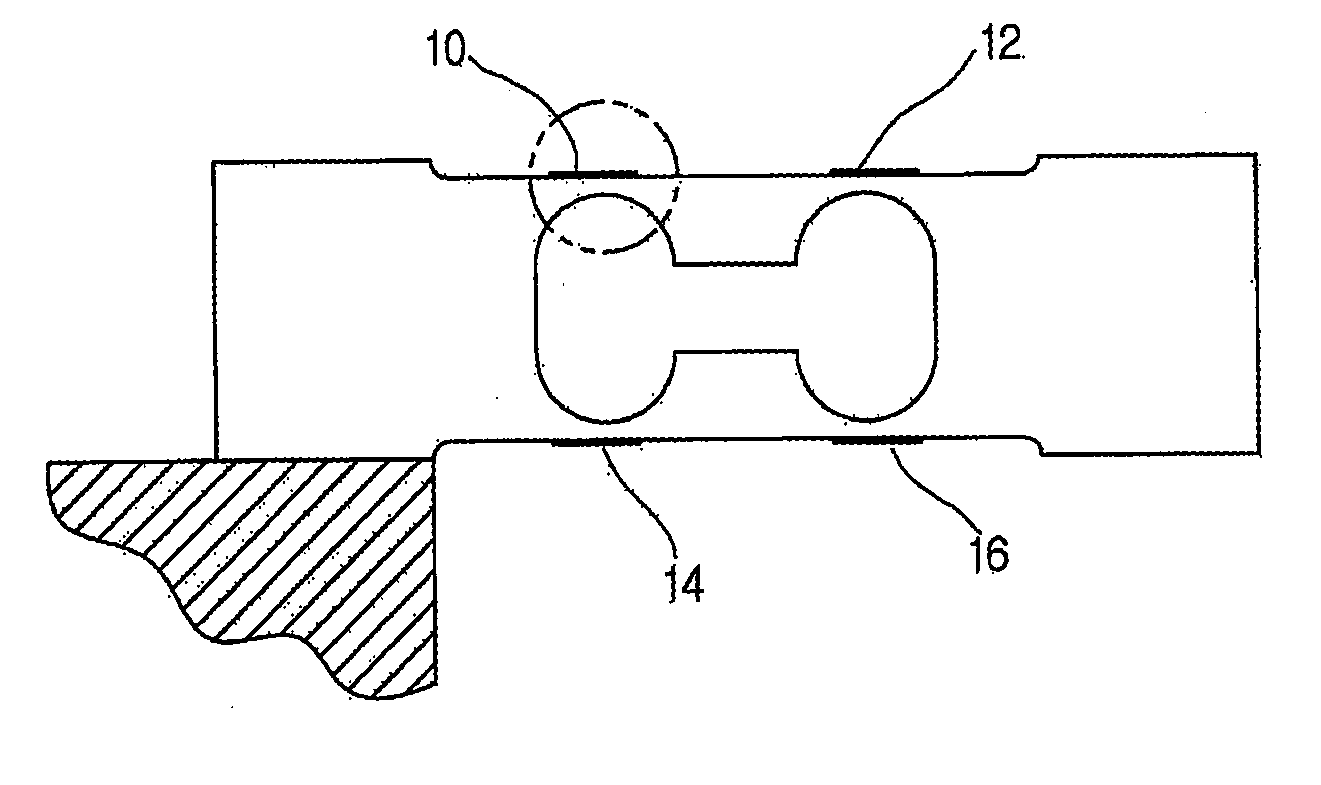
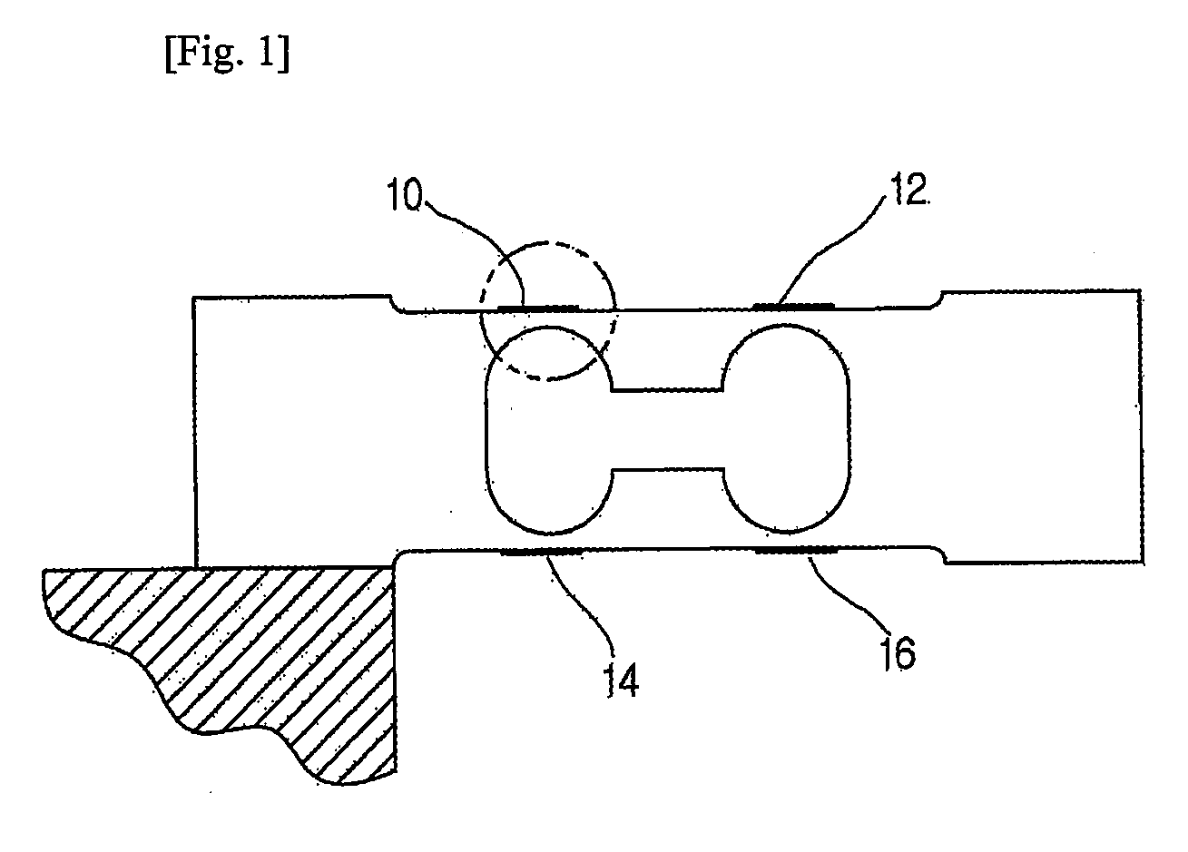
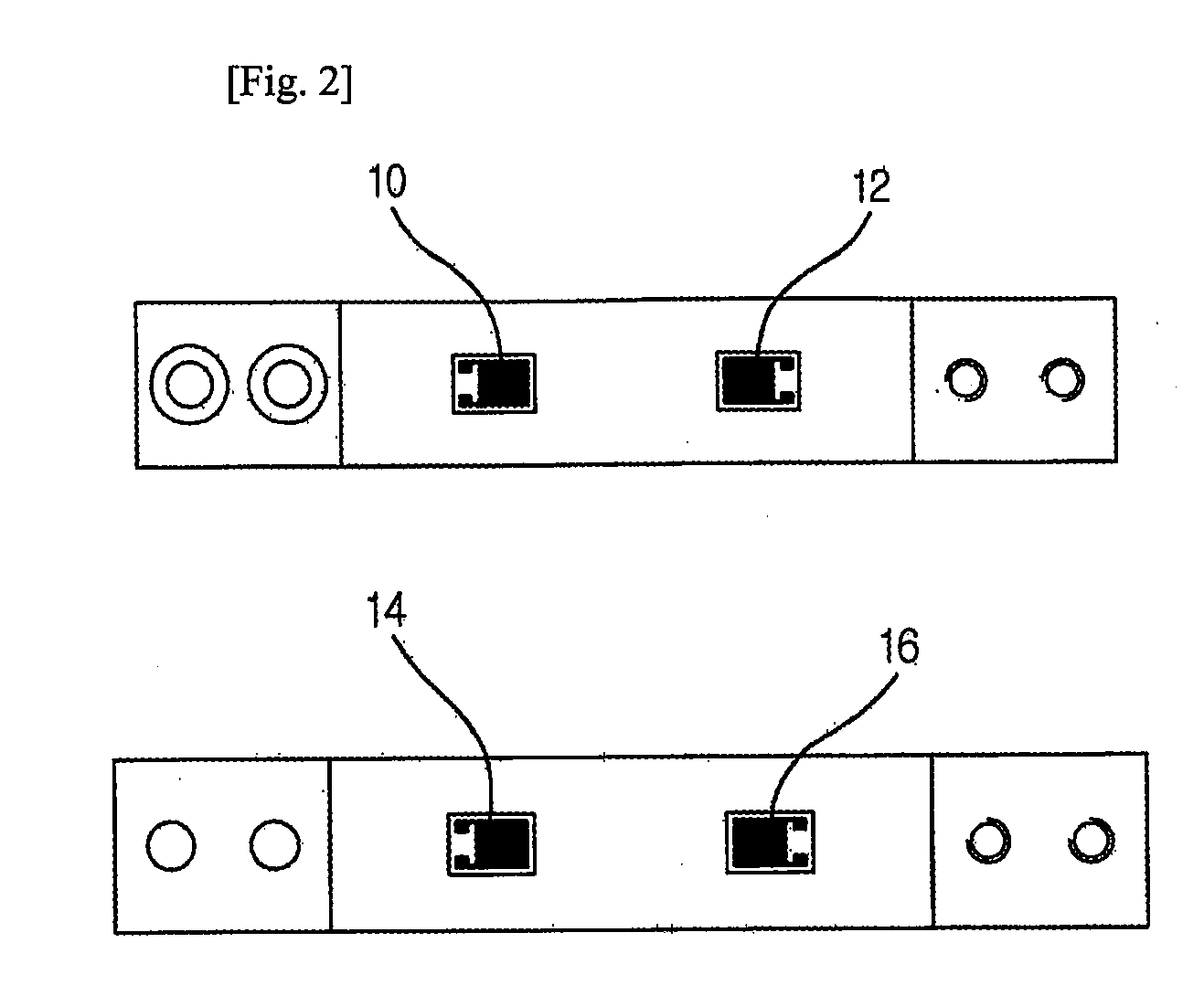
TECHNICAL FIELD[0001]The present invention relates to an elastic body for measuring loads and to a non-contact load-measuring device using the same. More particularly, the invention relates to an elastic body and a load-measuring device with which the precision for measuring load can be improved.BACKGROUND ART[0002]In the related art, the load cell is often used as a load-measuring device. FIG. 1 is a cross-sectional view of a load cell according to the related art, and FIG. 2 shows a top plan view (a) and a bottom plan view (b) of a load cell according to the related art.[0003]Referring to FIG. 1, on the upper and lower portions of a cantilever type elastic body, strain gauges 10, 12, 14, 16 may be attached using a polymer adhesive. The strain gauges may be electrically connected, and when a load is applied, the strain gauges may be deformed in correspondence to the deformation of the elastic body.[0004]FIG. 3 illustrates the changes that may occur when a load is applied on a load ...

Claims


Application Information

Patent Timeline
IPC IPC(8): G01L1/04
CPCG01G21/244G01G3/1404
Inventor SHIN, DONG-RYONGLEE, YOUN-SOK
Owner INVENTIO CO LTD
Learn More