Hydroconversion process for heavy and extra heavy oils and residuals
a hydroconversion process and heavy oil technology, applied in the direction of physical/chemical process catalysts, metal/metal-oxide/metal-hydroxide catalysts, etc., can solve the problem of high metal, sulfur and asphaltene content of hydroconversion processes in general for heavy residues, and cannot reach high conversion (more than 80 wt%) without recycling
- Summary
- Abstract
- Description
- Claims
- Application Information
AI Technical Summary
Benefits of technology
Problems solved by technology
Method used
Image
Examples
example 1
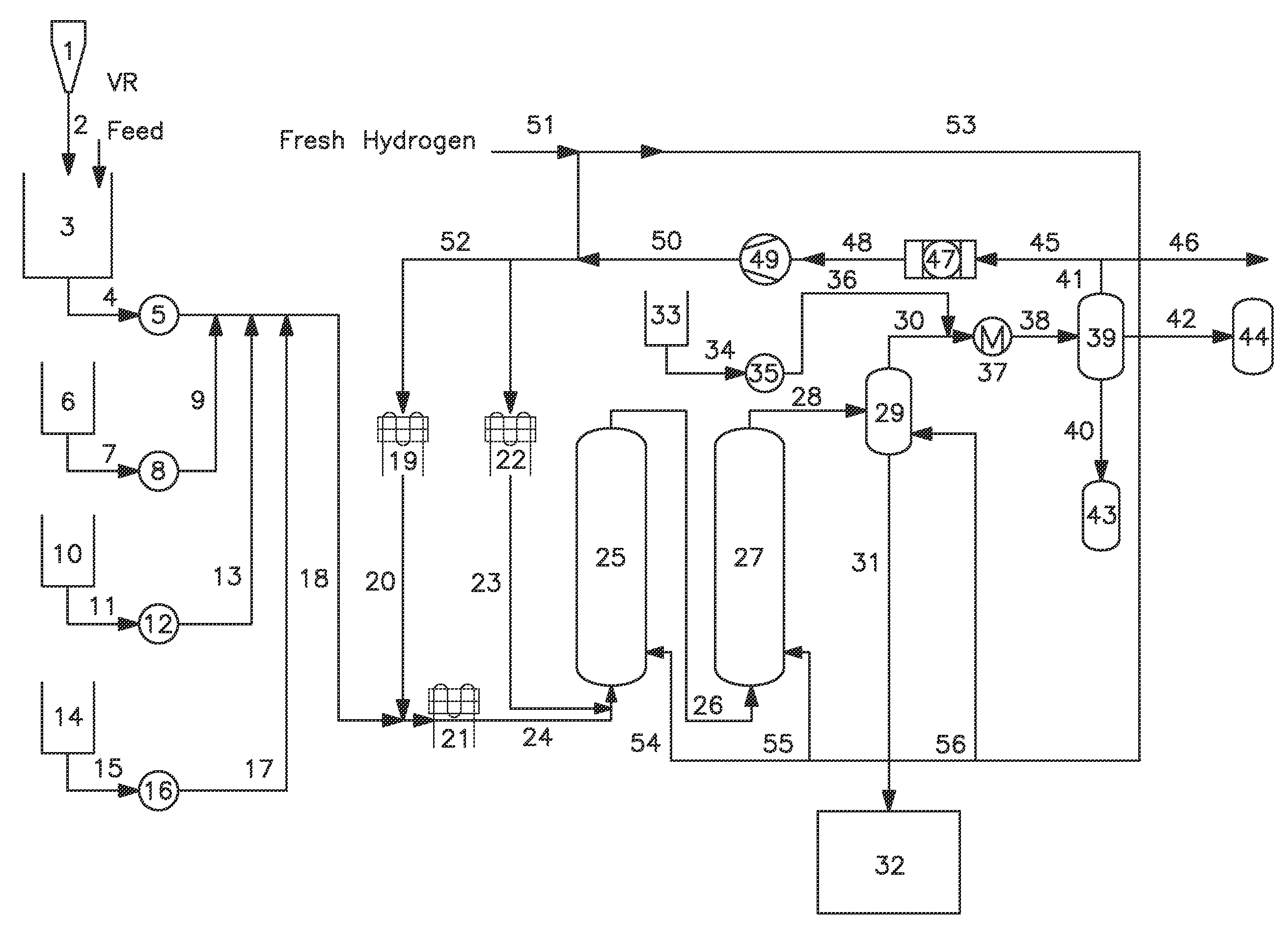
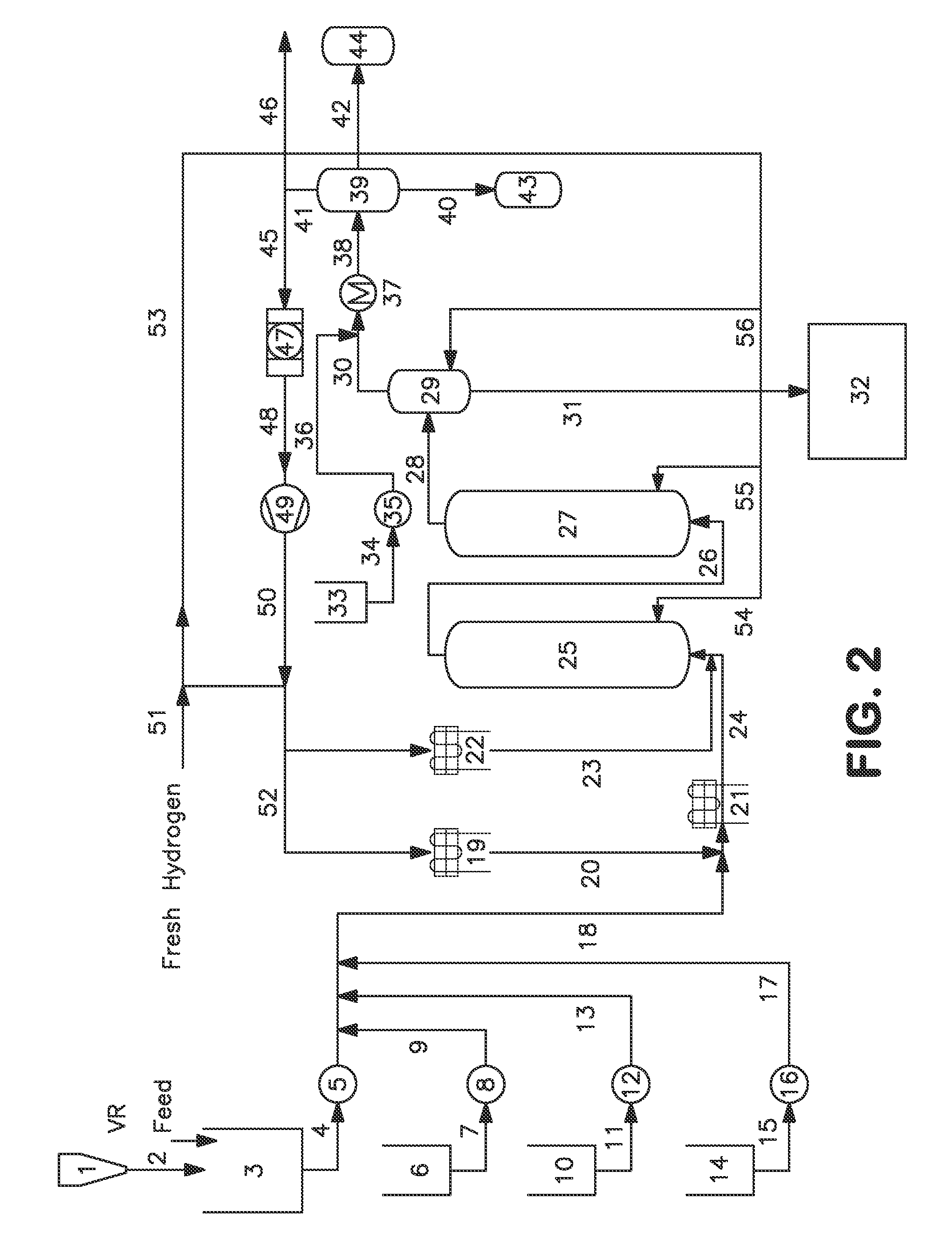
[0056]Following the scheme represented in FIG. 2, the following experiment was conducted.
[0057]A heavy feedstock comprised by a conventional vacuum residue (VR) of Venezuelan oil, Petrozuata, was fed into a reactor with a total capacity of 10 BPD. Said reactor was a slurry bubble column reactor without any internals, with a temperature control based on a preheater system and cool gas injection. This reactor has a length of 1.6 m and a diameter of 12 cm.
[0058]This reactor was operated at 0.52 T / m3 h (spatial velocity) at a total pressure of 170 barg, a gas to liquid ratio (H2 / liquid) of 32990 scf / bbl, a gas velocity of 5.98 cm / s. An organic additive was added to the feedstock in a concentration of 1.5 wt % and with a particle size ranging 200-300 μm. At these conditions, an ultradispersed catalyst was injected to the process to obtain 92 wtppm of nickel and 350 wtppm of molybdenum sulfide inside the reactor.
[0059]The average temperature inside the reactor was 458° C. The average resi...
example 2
[0063]Following the scheme represented in FIG. 2, the following experimentation was effected.
[0064]The test was carried out using a sample of vacuum residue (VR) of Canadian oil, prepared from Athabasca crude.
[0065]This VR was fed into a pilot plant with a total capacity of 10 BPD, with the same slurry bubble column reactor without any internals, as used in example 1, with a temperature control based on a preheater system and cool gas injection.
[0066]For this test the reactor was operated at two different spatial velocities of 0.42 and 0.73 T / m3 h. Three serially connected vertical slurry reactors were used during this test. The plant was in continuous operation during 20 days.
[0067]At 0.42 T / m3 h conditions were: total pressure of 169 barg, gas to liquid ratio (H2 / liquid) of 34098 scf / bbl, gas velocity of 7.48 cm / s, an organic additive concentration of 1.5 wt % with a particle size ranging 200-300 μm, with an injection of an ultradispersed catalyst to reach 92 wtppm of nickel and 3...
example 3
[0073]Following the scheme represented in FIG. 2, the following experimentation was effected.
[0074]This third test was carried out using a mixture of vacuum residue (VR) of Venezuelan oils, comprising Merey, Santa Barbara, Anaco Wax and Mesa.
[0075]This VR was fed into a pilot plant with a total capacity of 10 BPD, with the same slurry bubble column reactor without any internals of example 1, with a temperature control based on a preheater system and cool gas injection.
[0076]For this test the reactor was operated at two different spatial velocities of 0.4 and 0.5 T / m3 h, changing the catalyst and the solid concentration. Three serially connected vertical slurry reactors were used during this test. The plant was in continuous operation for 39 days.
[0077]At 0.4 T / m3 h spatial velocity, solids, catalysts and sulfur ammonium concentrations were changed, in the following table the results are summarized:
Feedstock characteristicsAPI density (60° F.)5.1Residue 500° C.+ (wt %)94.83Asphaltene...
PUM
| Property | Measurement | Unit |
|---|---|---|
| Temperature | aaaaa | aaaaa |
| Particle size | aaaaa | aaaaa |
| Temperature | aaaaa | aaaaa |
Abstract
Description
Claims
Application Information
 - R&D Engineer
- R&D Manager
- IP Professional
- Industry Leading Data Capabilities
- Powerful AI technology
- Patent DNA Extraction
Browse by: Latest US Patents, China's latest patents, Technical Efficacy Thesaurus, Application Domain, Technology Topic, Popular Technical Reports.
© 2024 PatSnap. All rights reserved.Legal|Privacy policy|Modern Slavery Act Transparency Statement|Sitemap|About US| Contact US: help@patsnap.com


