Parallel powering of portable electrical devices

Inactive Publication Date: 2011-05-26
O2 MICRO INC
View PDF10 Cites 66 Cited by
  • Summary
  • Abstract
  • Description
  • Claims
  • Application Information

AI Technical Summary

Benefits of technology

[0003]A wide variety of portable electrical devices are available today including, but not limited to, laptop computers, personal digital assistants, mobile phones, and cordless power tools. Such portable electrical devices may utilize a rechargeable battery for providing power to operate the device in a battery supply mode. An adapter such as an ACDC or DCDC adapter may also be available to supply power to the portable electrical device in an adapter supply mode. The rechargeable battery may or may not be charged in the adapter supply mode depending on the presence and condition of the rechargeable battery. In some instances, it is advantageous to supply a system load of the portable electrical device with power from both the adapter and the rechargeable battery. To do so, some conventional embodiments have controlled the output voltage of the adapter but have not adjusted the output voltage of the rechargeable battery.

Problems solved by technology

To do so, some conventional embodiments have controlled the output voltage of the adapter but have not adjusted the output voltage of the rechargeable battery.

Method used


Image

  • Parallel powering of portable electrical devices
  • Parallel powering of portable electrical devices
  • Parallel powering of portable electrical devices

Examples


Embodiment Construction

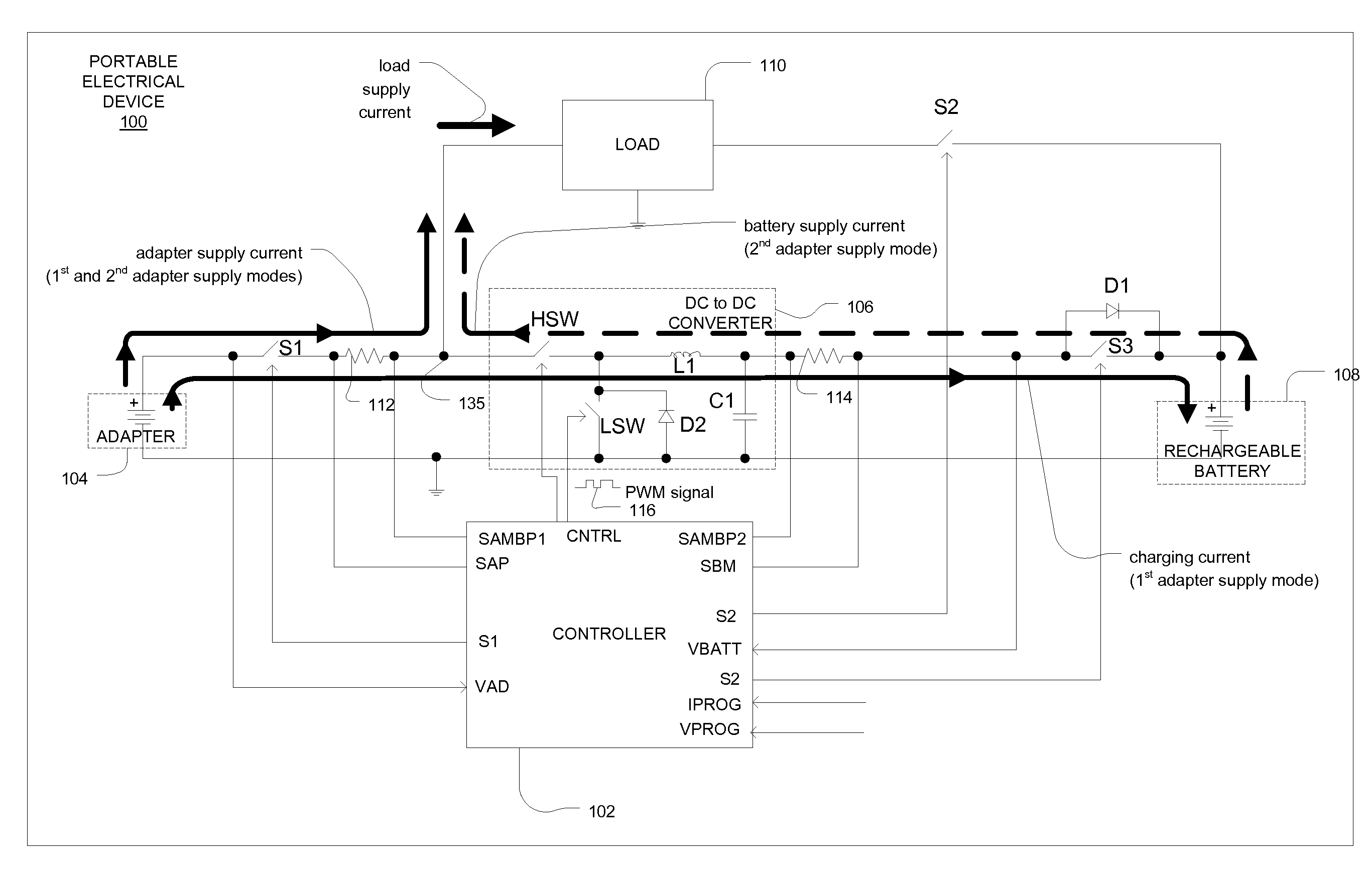
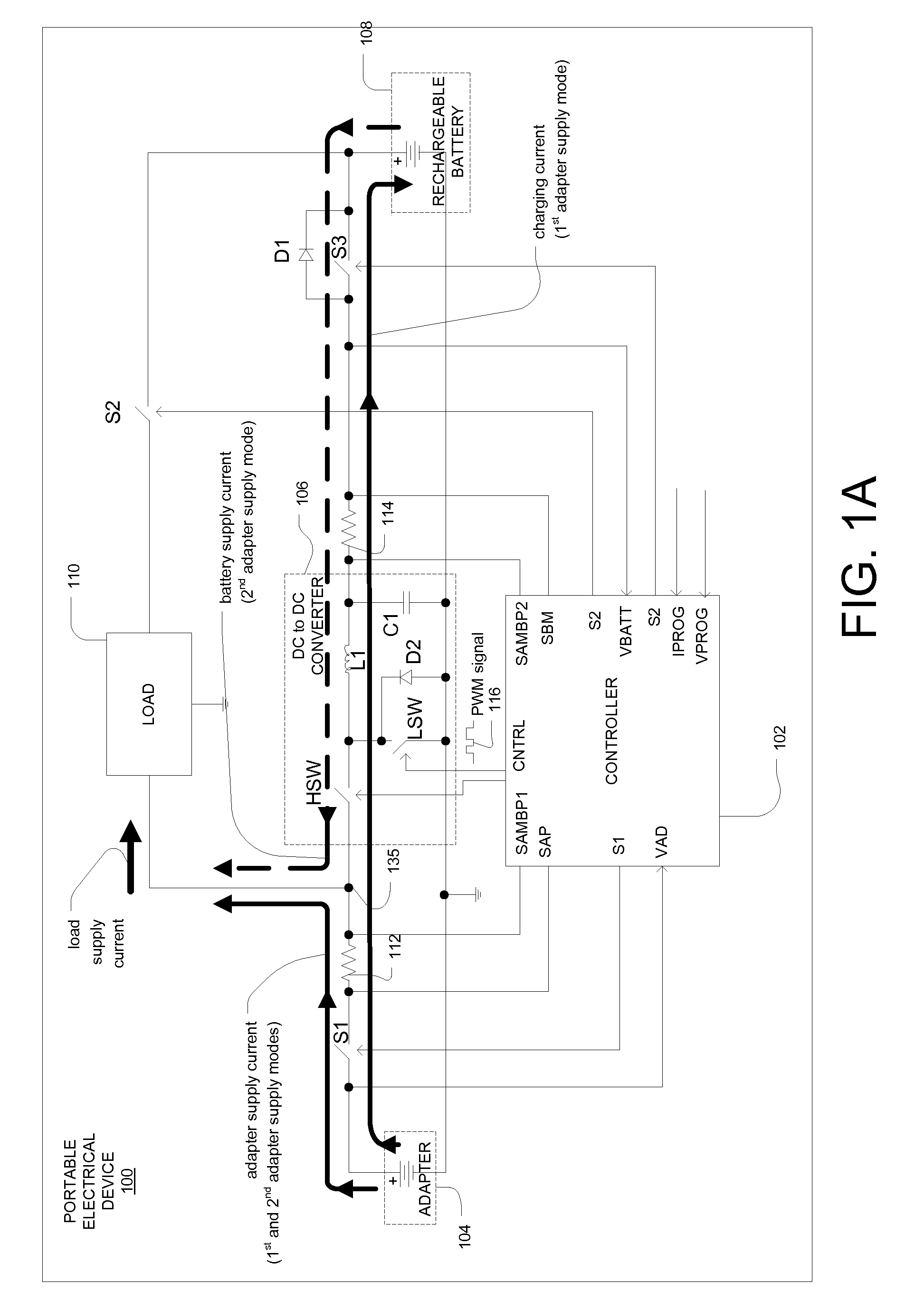
[0023]FIG. 1A is a block diagram of a portable electrical device 100. The portable electrical device 100 may include, but not be limited to, laptop computers, personal digital assistants, mobile phones, and cordless power tools. The portable electrical device 100 may include an adapter 104, a rechargeable battery 108, a load 110, a DC to DC converter 106, and a controller 102. In general, the controller 102 may be configured to control the DC to DC converter 106 to operate in two different adapter supply modes when the adapter 104 and rechargeable battery 108 are present.

[0024]In a first adapter supply mode, the DC to DC converter 106 may be configured to provide a charging current to the rechargeable battery 108. In a second adapter supply mode, the DC to DC converter 106 may be configured to provide a battery supply current to the system load 110 via the common node 135. In both the first and second adapter supply modes, the adapter 104 may provide an adapter supply current to the...


PUM


Abstract

A system may include an electronic device configured to consume a supply current; an AC to DC adapter configured to be coupled to the electronic device, wherein the AC to DC adapter has a maximum rated output current; a battery configured to be coupled to the electronic device; DC to DC converter configured to be coupled to the battery and the electronic device; and a controller configured to couple the AC to DC adapter to the electronic device, the controller further configured to couple the DC to DC converter to the battery and the electronic device when the supply current exceeds the maximum rated output current of the AC to DC adapter.

Description

CROSS REFERENCE TO RELATED APPLICATIONS[0001]This is a continuation-in-part of, and claims the benefit of, U.S. application Ser. No. 11 / 283,088, filed Nov. 18, 2005, now U.S. Pat. No. 7,719,236, which claims benefit of U.S. Provisional Application No. 60 / 654,750 filed Feb. 18, 2005, the teachings all of which are incorporated herein by reference.FIELD[0002]The present disclosure relates to portable electrical devices and, more particularly, to parallel powering of such devices.BACKGROUND[0003]A wide variety of portable electrical devices are available today including, but not limited to, laptop computers, personal digital assistants, mobile phones, and cordless power tools. Such portable electrical devices may utilize a rechargeable battery for providing power to operate the device in a battery supply mode. An adapter such as an ACDC or DCDC adapter may also be available to supply power to the portable electrical device in an adapter supply mode. The rechargeable battery may or may ...

Claims


Application Information

Patent Timeline
Patent Type & Authority Applications(United States)
IPC IPC(8): H02J9/00H02J7/00H02J1/00
CPCH02J1/10H02M3/156H02J7/34H02J7/00H02J7/0068
Inventor HARTULAR, ALEXANDRULIPCSEI, LASZLONICULAE, MARIANSPIRIDON, CONSTANTIN
Owner O2 MICRO INC
Why Eureka
Try Eureka