
Underdesk apparatus for organizing electronics and connections

a technology for electronics and connections, applied in the field of office equipment, can solve the problems of wasting desk space, creating a rat-nest of wires, cables and boxes, and difficulty in organizing electronics and connections with home office and small office computer systems, and achieve the effect of easy release or movement, and no risk of falling

Inactive Publication Date: 2006-12-14
RAST RODGER H
View PDF0 Cites 33 Cited by
  • Summary
  • Abstract
  • Description
  • Claims
  • Application Information

AI Technical Summary

Benefits of technology

[0016] Another aspect of the invention is to provide a system for retaining a range of power supplies and small electronics beneath a desk, while allowing those items to be readily released or moved.
[0017] Another aspect of the invention is to retain power supplies within a power strip and assure their retention without risk of falling.

Problems solved by technology

Currently it is difficult to organize the electronics and connections needed with home office and small office computer systems.
In typical installations power strips often lie on the ground and connections are strewn about between the various elements, creating a rats-nest of wires cables and boxes.
Many problems arise as desk space is usually at a premium and the clutter and tangle of connections unsightly.
Installing AC power adapters into vertical or inverted positions often leads to loss of connection, and the risk of personal or equipment damage.
Current desk practices allow connections to dangle, get banged around, get snagged and damaged.
In addition, it should be appreciated that the jungle of wiring of connections is subject to damage, disconnection, and possibly injuries.

Method used


Image

  • Underdesk apparatus for organizing electronics and connections
  • Underdesk apparatus for organizing electronics and connections
  • Underdesk apparatus for organizing electronics and connections

Examples


embodiment 10

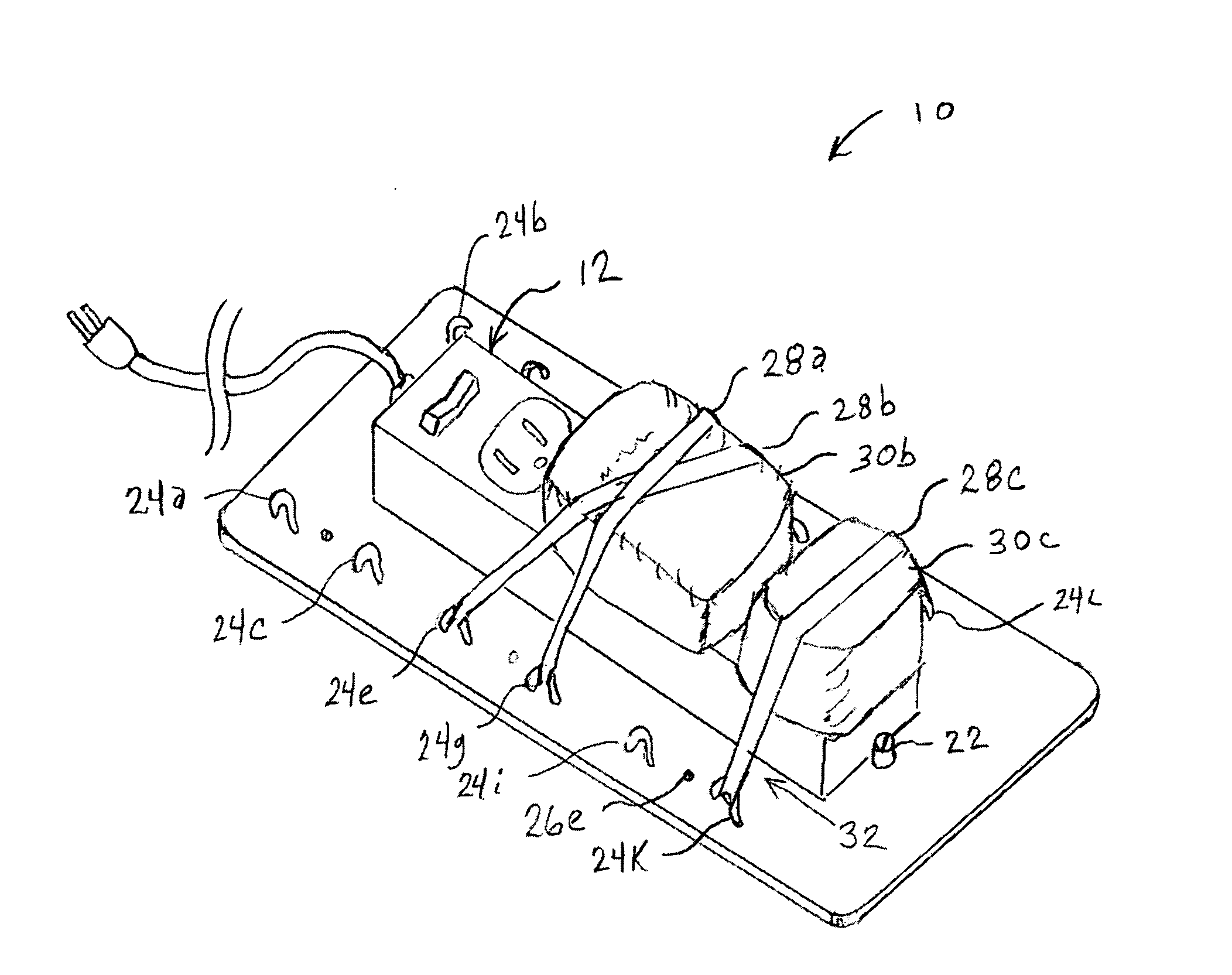
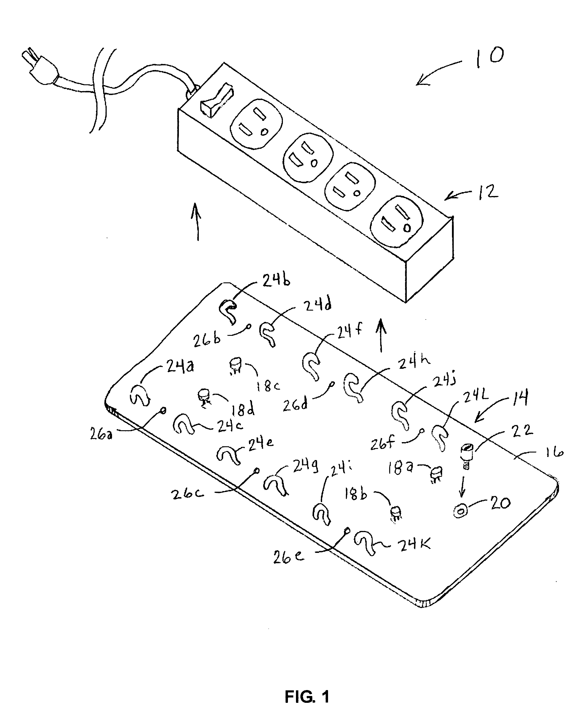
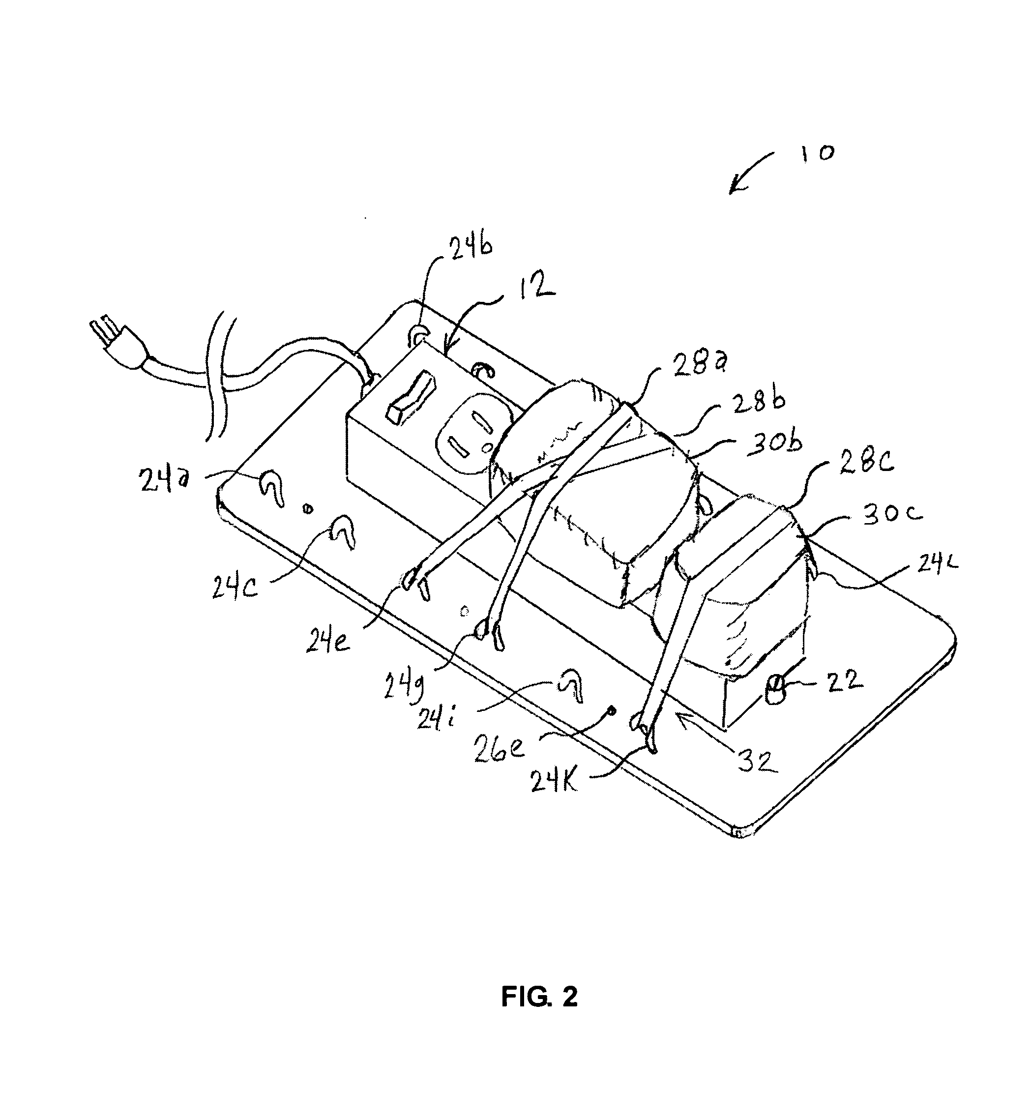
[0051]FIG. 1 illustrates by way of example, a power strip clasper embodiment 10 that is particularly well suited for mounting a power strip to a desk. A power strip 12 is shown having a number of AC outlets for mounting AC power modules and establishing AC connections. The embodiment has a power retention clasper body 14 formed from a substantially planar material 16, preferably a stiff material. A device interface is exemplified in this figure as a fixed number of plastic nubs 18 for insertion within mounting holes of the power-strip, such as by slipping them in and sliding the power strip in one direction. A locking means is preferably provided, such as comprising a locking pin 22 for retention within a locking structure 20, such threadably engaged although other clasp, slider, and similar mechanisms can be substituted.

[0052] Extending from base 14 is also a plurality of releasable band retention members (BRMs) 24a-24L, which are depicted in this example having curving heads adapt...

embodiment 40

[0057]FIG. 3 illustrates an embodiment 40 of a specialized short power connector for use with power packs 42 to be mounted with the system. There is often insufficient room for mounting large AC power packs directly into the AC power strip. However, connecting them remotely leads to having an overly long connection and to the possibility that either or both ends of the connection can work loose.

[0058] This aspect of the invention provides a mechanism for securely mounting these AC power packs under the desk while maintaining aesthetics. Connector 40 is shown with a plate 44 extending from a female power receptacle 46 from which the AC wire bundle extends to a male plug end 48. It will be appreciated that elastic bands retaining power module 42, such as according to the device shown in FIG. 5, or FIG. 4 or FIG. 7, can be oriented over plate 44 therein retaining a tight connection with the power pack while retaining the pack to the desk. In one embodiment of the invention plate 44 can...

embodiment 200

[0081]FIG. 12 illustrates an alternate embodiment 200 wherein each of the pivoting assemblies 166 of FIG. 8, or 188 in FIG. 9, are replaced with a retraction spool 206 for selectively retaining strap 204. The use of retraction spools 206 allows keeping the strap held close beneath the desk (Position A shown in phantom) when not in use.

[0082] Preferably a “toe insertion gap” is formed allowing the user to insert the tip of one foot to pull the device into the active position. Straps 204 may be a single strap of any desired cross-section or multiple straps. In one embodiment the straps comprise a planar nylon belt material having a tensile strength preferably at or exceeding about 100-200 pounds.

[0083] The reels can be configured to extend only in response to sufficient pressure, wherein upon the user removing their feet from the device it automatically retracts. Alternatively, the reels can provide controlled retraction using a latching means which is responsive to user input by way...


PUM


Abstract

An under desk system is described for mounting electrical devices and their cords to home and office furniture, in particular beneath the desk to remove the clutter and mess often strewn about a computer laden desk. By way of example a rigid planar base member is adapted with engagement structures to retain a power strip, and further adapted with a plurality of band retention fingers configured for engaging elastic bands for being strapped between retention fingers on opposite sides of the power strip to retain AC adapters plugged into the power strip. Devices are also described for retaining modems, routers, wireless communication ports, and other small electrical devices to vertical surfaces, or more preferably beneath desk or other furnishings. These devices can be manufactured using molding processes or any other desired methods.

Description

CROSS-REFERENCE TO RELATED APPLICATIONS [0001] This application claims priority from provisional patent application Ser. No. 60 / 678,732 filed May 6, 2005.STATEMENT OF FEDERALLY SPONSORED RESEARCH OR DEVELOPMENT [0002] Not Applicable REFERENCE TO A MICROFICHE APPENDIX [0003] Not Applicable BACKGROUND OF THE INVENTION [0004] 1. Field of the Invention [0005] This invention pertains generally to office equipment and more particularly to office and desk accessories. [0006] 2. Description of the Background Art [0007] Currently it is difficult to organize the electronics and connections needed with home office and small office computer systems. A number and variety of desk electronics must be positioned proximal to the desk and connected. The electronics can comprise peripherals (e.g., displays, printers, scanners, tablets, audio equipment, camera caddies, PDA ports and so forth), communications devices (e.g., telephones, voice recorders, Caller ID units, Faxes, modems, hubs, routers, gate...

Claims


Application Information

Patent Timeline
Patent Type & Authority Applications(United States)
IPC IPC(8): A47B91/00B65D19/00A47G29/00
CPCA47B21/06H01R25/003H01R13/6392
Inventor RAST, RODGER H.
Owner RAST RODGER H
Learn More