Rotating clip orthodontic bracket

a technology of orthodontic brackets and rotating clips, which is applied in the field of locking orthodontic brackets, can solve the problems of increasing the size of the locking cover, the user cannot be certain as to the proper seating of the archwire, and the user's visual confirmation of the proper placement of the archwire, so as to reduce calculus build up and the effect of affecting the stability of the bracket, reducing the amount of calculus

Active Publication Date: 2011-05-26
ORMCO CORP
View PDF1 Cites 55 Cited by
  • Summary
  • Abstract
  • Description
  • Claims
  • Application Information

AI Technical Summary

Benefits of technology

[0013]In a preferred embodiment, the tips of the wings enclose an orthodontic arch wire within the arch wire slot of the orthodontic bracket when the rotating clip is rotated counterclockwise. A clockwise rotation of the rotating clip opens the arch wire slot for placement or removal of the orthodontic arch wire. The strength transmitted to the wing tip is partially derived from the circular shape of the attached cylindrical body and the intimate fitting of the cylindrical body within the circular recess. The resulting strength is increased allowing the wings to be thinner which is advantageous for patient comfort. The underside of the wing, in one embodiment, has a bump that actively holds the archwire in the slot, as opposed to passively holding the archwire when the underside of the wing is flat. In another embodiment the rotating clip has two sets of wings wherein one pair actively engage the archwire when the rotating clip is rotated in one direction and passively holds the archwire when the rotating clip is rotated in the opposite direction. In another preferred embodiment, the locking clip wing is shaped to enclose most of the arch wire in the archwire slot. In another preferred embodiment, the underside of the locking clip wing contains a bevel to push the arch wire into the arch wire slot. In a further embodiment, the underside of the wing contains bumps for active clip design.
[0014]The bracket wall that retains the rotating clip remains open to self cleanse, reducing calculus build up and stuck moving parts. Tooth brush bristles can access the walls of bracket body. The bracket body design remains the same for both active and passive and active passive designs. The design allows the clinician to go from passive to active to conventional and back at any point in treatment. Height gauges may be used conventionally. The rotating clip does not interfere with anatomical structures, such as gums and other teeth, when in the open position. The rotating clip orthodontic bracket may be comprised of metal, plastic or ceramic or combinations thereof. Equivalent materials may be used. MIM technology can be used for the bracket body wherein retention for the clip is built within and there is a potential to use a breakaway design in MIM for one piece bracket body assembly. The door design will allow only the mesial or distal aspect of wing to be engaged on severely rotated teeth as the wing door can close around one wing while leaving the wire exiting the center of the bracket. The wire can be engaged from both the gingival and the occlusal in door design

Problems solved by technology

Sliding closures require the archwire also to be recessed within the archwire slot before the closure can be moved over the archwire making it very difficult for the user to visually confirm that the archwire is properly seated within the archwire slot.
Without this visual access being clear, one installing an archwire within a bracket cannot be certain as to proper seating of an archwire within the archwire slot before the slide cover is moved to a closed position.
A drawback of many self-ligating brackets the locking covers increase the size of the bracket.
There are other means that are more complex and difficult and expensive to manufacture.
Springs used as locking means are not strong enough to hold the arch wire into the slot.

Method used


Image

  • Rotating clip orthodontic bracket
  • Rotating clip orthodontic bracket
  • Rotating clip orthodontic bracket

Examples


Embodiment Construction

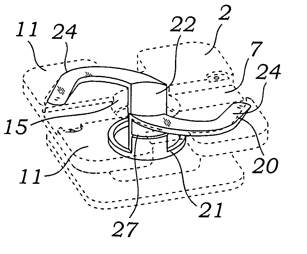
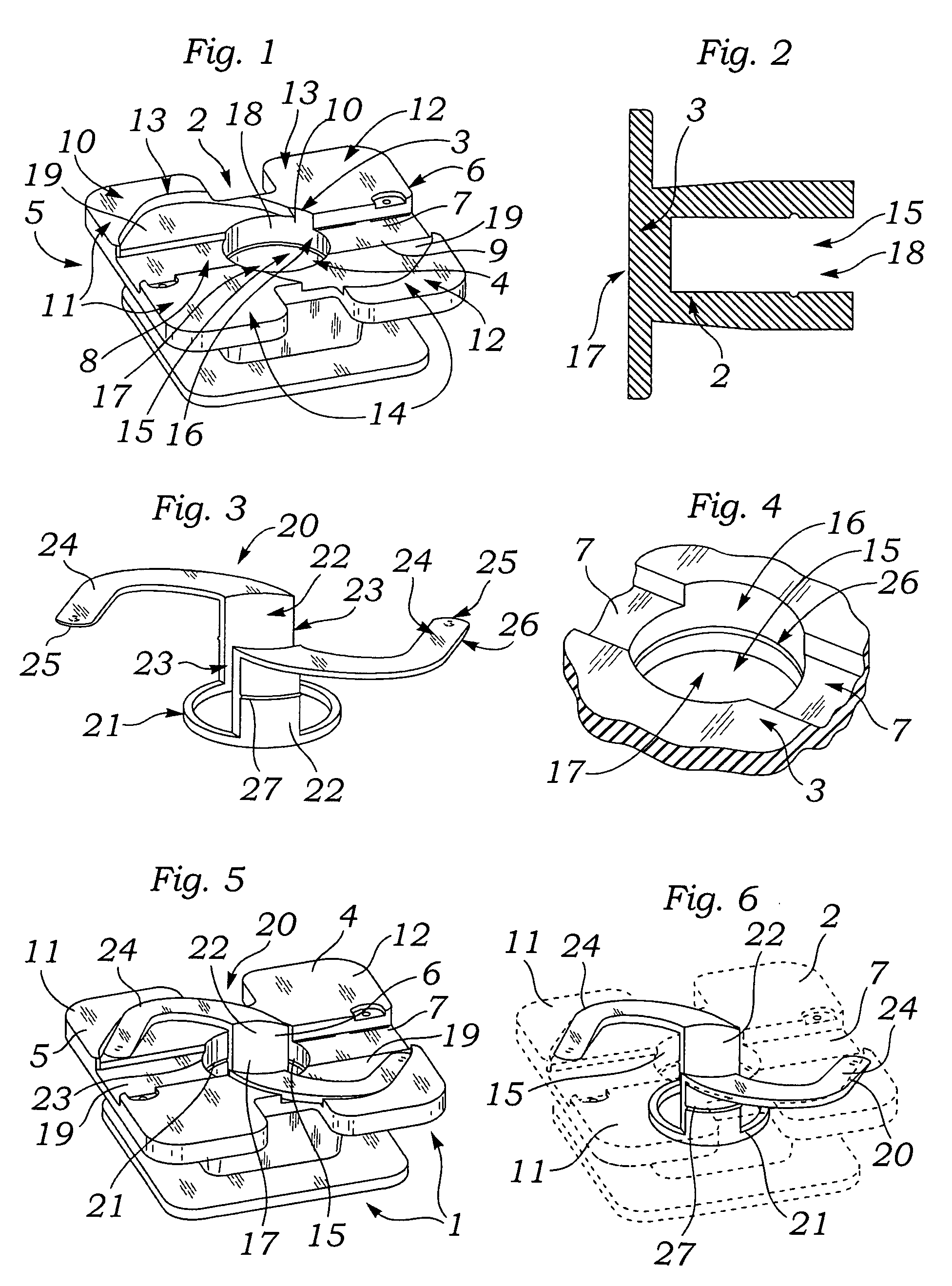
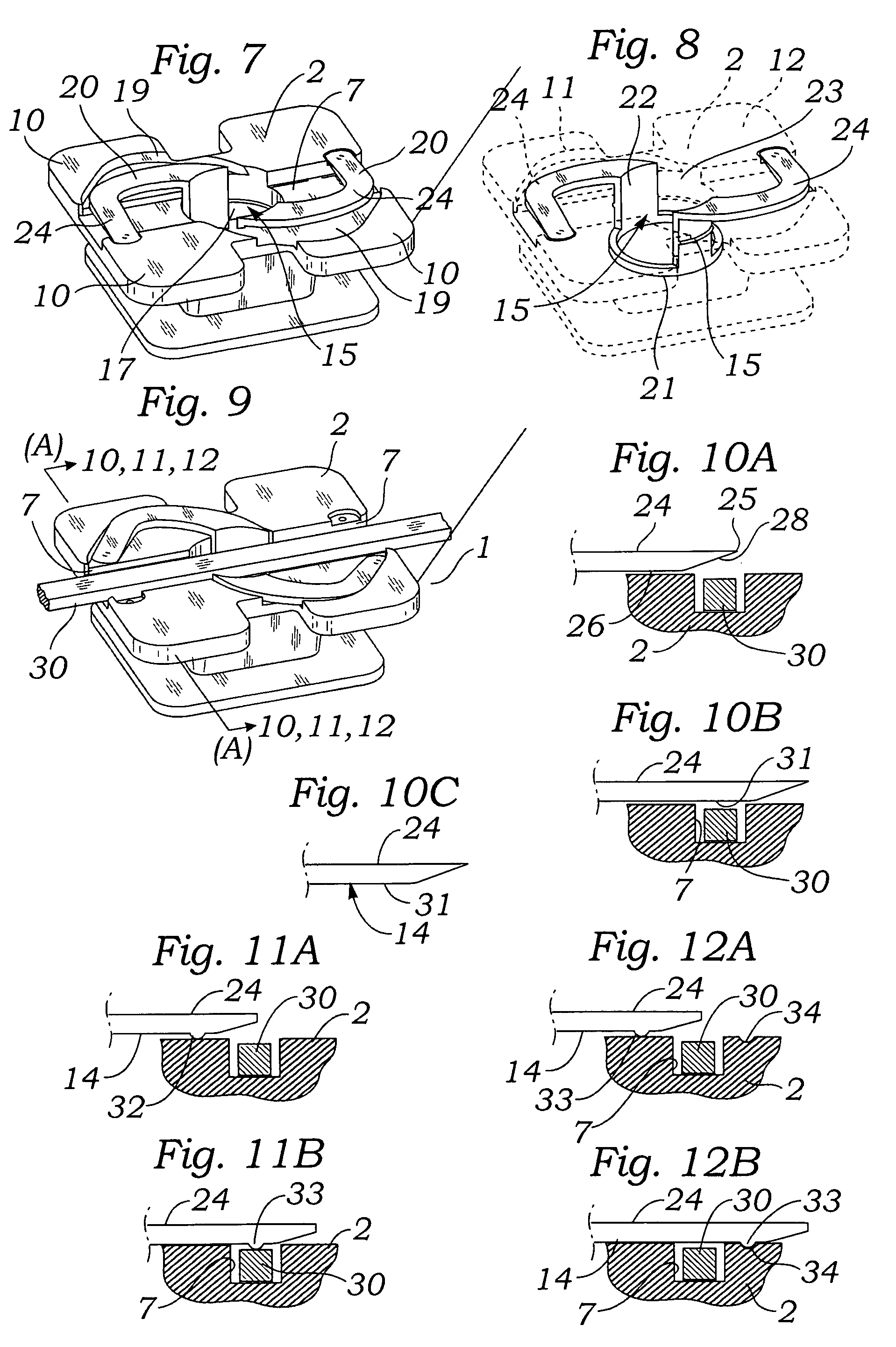
[0042]The invention is comprised of a self-ligating orthodontic bracket assembly 1. FIG. 1 discloses a bracket body 2 with a back 3 and a front surface 4. The bracket body 2 has a left side 5 and right side 6. An archwire slot 7 extends from left 8 to right 9 on the front surface 3. Attached to the bracket body 2 are tie wings 10 positioned left 11 and right 12. The tie wings 10 extend outwardly from the top 13 and bottom14. The front surface 4 of the bracket body 2 contains a cylindrical recess 15 with a circular wall 16 extending from a circular front 17 towards the body 2 back 3 ending in a circular floor. The tie wings 10 fit within front surface 4 recesses 19 in order to make the tie wings 10 flush with the bracket front surface 4. FIG. 2 shows the bracket body 2 in cross section. FIG. 3 discloses a rotating clip 20 which is attached into the cylindrical recess 15 of FIGS. 1 and 2. The rotating clip 20 has a circular base 21 with attached opposing columns 22 extending at right ...


PUM


Abstract

The present invention is directed to a locking orthodontic bracket that contains a mechanism that rotationally locks an orthodontic archwire fully or partially within the bracket archwire slot.

Description

FIELD OF THE INVENTION[0001]The present invention is directed to a locking orthodontic bracket that contains a mechanism that rotationally locks an orthodontic archwire within the bracket archwire slot.BACKGROUND OF TILE INVENTION[0002]Orthodontic brackets attached to teeth transmit forces, such as produced by an archwire, to move the teeth. Brackets usually contain an archwire slot for reception of the archwire. Orthodontic brackets today are typically bonded to a tooth or welded to an orthodontic band that is cemented to the tooth.[0003]Brackets commonly use tie wings that project upwardly and downwardly in pairs at the top and bottom of the installed bracket, respectively. These wings permit the archwire to be held within the archwire slot of the bracket by means of a twisted wire (ligature) or an elastomeric o-ring. Currently there are varieties of brackets that are self-ligating. These self-ligating brackets have taken several forms.[0004]U.S. Pat. No. 5,094,614 to Wildman, iss...

Claims


Application Information

Patent Timeline
Patent Type & Authority Applications(United States)
IPC IPC(8): A61C7/28
CPCA61C7/285
Inventor RUDMAN, ROBERT T.
Owner ORMCO CORP
Why Eureka
Try Eureka