Drip chamber with flow control

a flow control and drip chamber technology, applied in the direction of valve operating means/release devices, process and machine control, instruments, etc., can solve the problems of affecting the flow rate, and the roller clamp may be almost non-effective when used with non-pvc tubing

Active Publication Date: 2011-05-26
BAXTER INT INC +1
View PDF32 Cites 61 Cited by
  • Summary
  • Abstract
  • Description
  • Claims
  • Application Information

AI Technical Summary

Benefits of technology

[0039]FIG. 17 is a schematic diagram of a system for electronically regulating a flow control system of the present disclosure.

Problems solved by technology

Over time, the stress induced in the tubing and creep effects gradually alter the resiliency and dimensions of the tubing, altering the flow rate as set by the health care provider using the roller clamp.
The effects of stress and creep are particularly profound when non-PVC tubing is used, such that roller clamps may be almost non-effective when used with non-PVC tubing.
Another drawback of using roller clamps is the difficulty in setting the flow rate of a liquid limited patient such as a neonatal patient.
The tubing clamp is ill suited for such setting as even a slight movement of the roller can lead to a more than desired change in the flow rate thereby leading to multiple slight movements of the roller to set such a rate.
This prolongs the time needed to set the rate.
In addition, even a slight creep over time caused by the roller clamp can result in a change in the flow rate bringing it outside the desired range.
A further drawback of conventional flow control systems is the possibility of providing a closed loop fluid control to the flow control system.
Roller clamps are configured to be manipulated by the health care provider and are problematic to incorporate into an automatic system which may manipulate the clamp in dependence on sensed parameters such as the monitored flow or condition of the patient.
Further, over time the roller 22 may induce stresses and creep effects in the tubing, causing fatigue or otherwise degrading the tubing, diminishing the precision and effectiveness of the roller clamp 20 in controlling flow rate through the tubing 18 or requiring additional monitoring In addition, such conventional flow control systems generally do not permit variation in accordance with the particular needs of the individual patient; that is, the same tubing-and-roller-clamp system may be used with an adult receiving a therapy with a wide treatment range or with an infant receiving a therapy that must be kept within a narrow treatment range.

Method used


Image

  • Drip chamber with flow control
  • Drip chamber with flow control
  • Drip chamber with flow control

Examples


embodiments

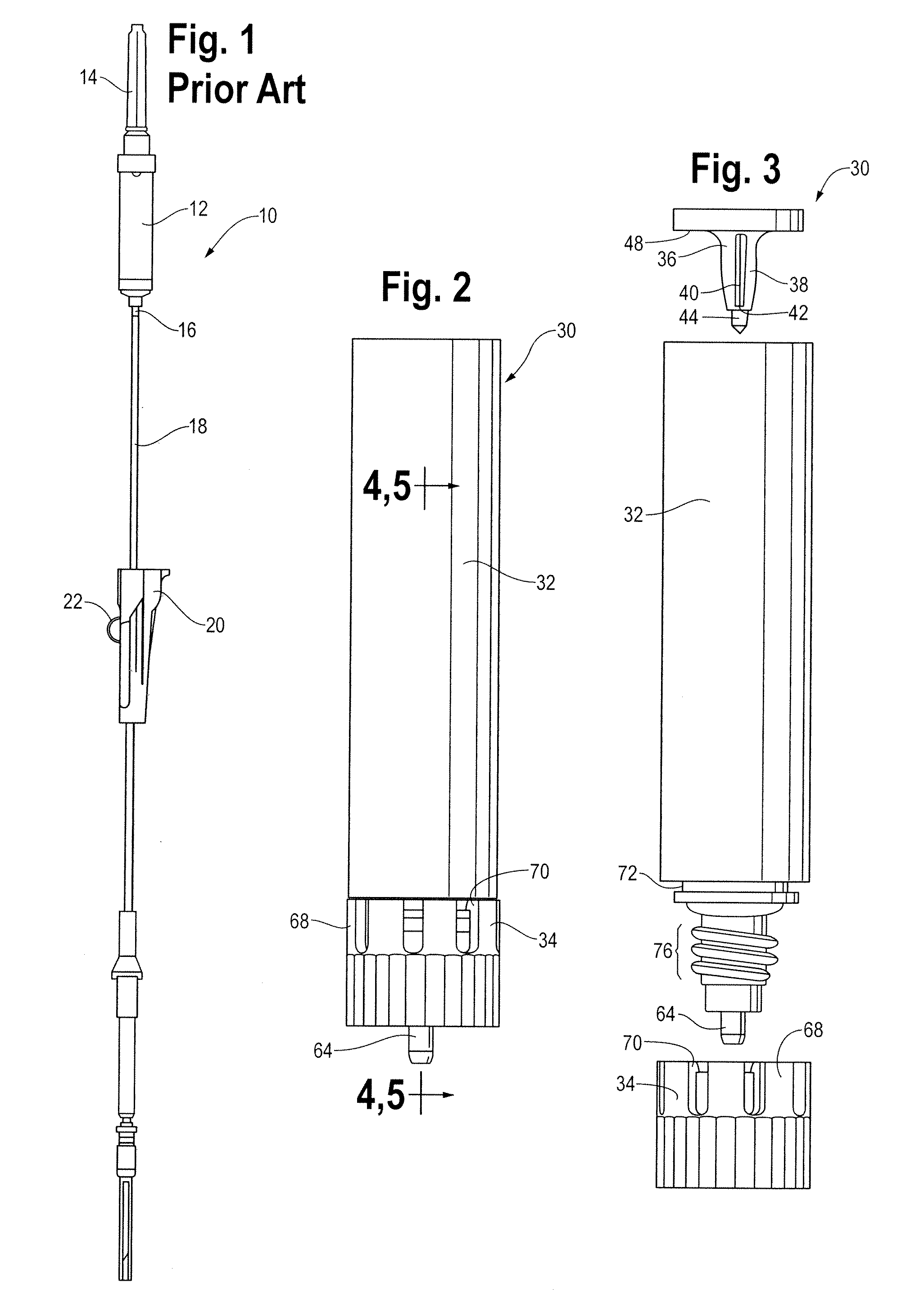
[0048]A conventional flow control system 10 for use in perfusion, transfusion or infusion applications is illustrated in FIG. 1. The flow control system 10 includes a drip chamber 12 having a spiked inlet or upstream end 14 and an outlet or downstream end 16, a length of tubing 18 extending from the outlet 16 of the drip chamber 12, and a roller clamp 20 provided along the length of the tubing 18, downstream of the outlet 16 of the drip chamber 12. The roller clamp 20 includes a roller 22 that pinchingly deforms the tubing 18 to alter the flow rate of fluid through the tubing 18.

[0049]As discussed in the Background section, the precision of such devices is directly dependent upon intensive monitoring of the system over time by the health care provider. Further, over time the roller 22 may induce stresses and creep effects in the tubing, causing fatigue or otherwise degrading the tubing, diminishing the precision and effectiveness of the roller clamp 20 in controlling flow rate throu...


PUM


Abstract

A flow control system includes a drip chamber having lower and upper wall sections and a collapsible wall extending between the lower and upper wall sections, a downwardly depending valve seat attached to the lower wall section, and a valve member disposed in the drip chamber, attached to the upper wall section and having a valve surface engageable with the valve seat. The system also includes a driver rotatably engaged to the lower and upper wall sections. Upon rotation of the driver in a first direction, the collapsible wall of the drip chamber moves between a collapsed condition in which the valve seat is sealingly engaged with the valve surface and an extended condition in which the valve seat is sufficiently spaced from the valve surface to form a flow passageway between the valve surface and the valve seat and permit flow through the opening of the drip chamber.

Description

REFERENCE TO RELATED APPLICATIONS [0001]This application claims the benefit of U.S. Application No. 61 / 264,376, filed Nov. 25, 2009, which is hereby incorporated by reference in its entirety herein.FIELD OF THE DISCLOSURE [0002]This disclosure relates generally to systems for regulating the flow of fluid through a fluid set into a patient and, more specifically, to devices for achieving precise control over a range of flow rates of fluids delivered in perfusion, transfusion, and infusion systems.BACKGROUND [0003]Many conventional flow control systems for perfusion, transfusion, and infusion systems are provided by the use of a flow regulator in the form of a roller clamp attached to tubing leading from a drip chamber to the patient. Such roller clamps rely on deformation of the tubing to modify the fluid flow path in order to slow down or speed up the rate of flow to the patient. Over time, the stress induced in the tubing and creep effects gradually alter the resiliency and dimensi...

Claims


Application Information

Patent Timeline
Patent Type & Authority Applications(United States)
IPC IPC(8): A61M5/168
CPCA61M5/1411A61M5/16881A61M5/16804
Inventor RONDEAU, GEORGES
Owner BAXTER INT INC
Why Eureka
Try Eureka