Exhaust apparatus for transverse engine

a technology for exhaust gas purification and apparatus, which is applied in the direction of mechanical apparatus, engine components, machines/engines, etc., can solve the problem of difficult to quickly raise the temperature of catalysts in exhaust gas purification units, and achieve the effect of raising the temperature of catalysts

Active Publication Date: 2011-06-02
MAZDA MOTOR CORP
View PDF4 Cites 6 Cited by
  • Summary
  • Abstract
  • Description
  • Claims
  • Application Information

AI Technical Summary

Benefits of technology

The present invention has been made in view of the above background art. It is therefore an object of the present invention to, in an exhaust apparatus for a transverse engine, make it possible to compactly lay out an exhaust upstream

Problems solved by technology

Moreover, in the arrangement where the exhaust gas-purifying unit is provided inside the tunnel portion, a traveling wind produced by traveling of a vehicle is more likely

Method used


Image

  • Exhaust apparatus for transverse engine
  • Exhaust apparatus for transverse engine
  • Exhaust apparatus for transverse engine

Examples


first embodiment

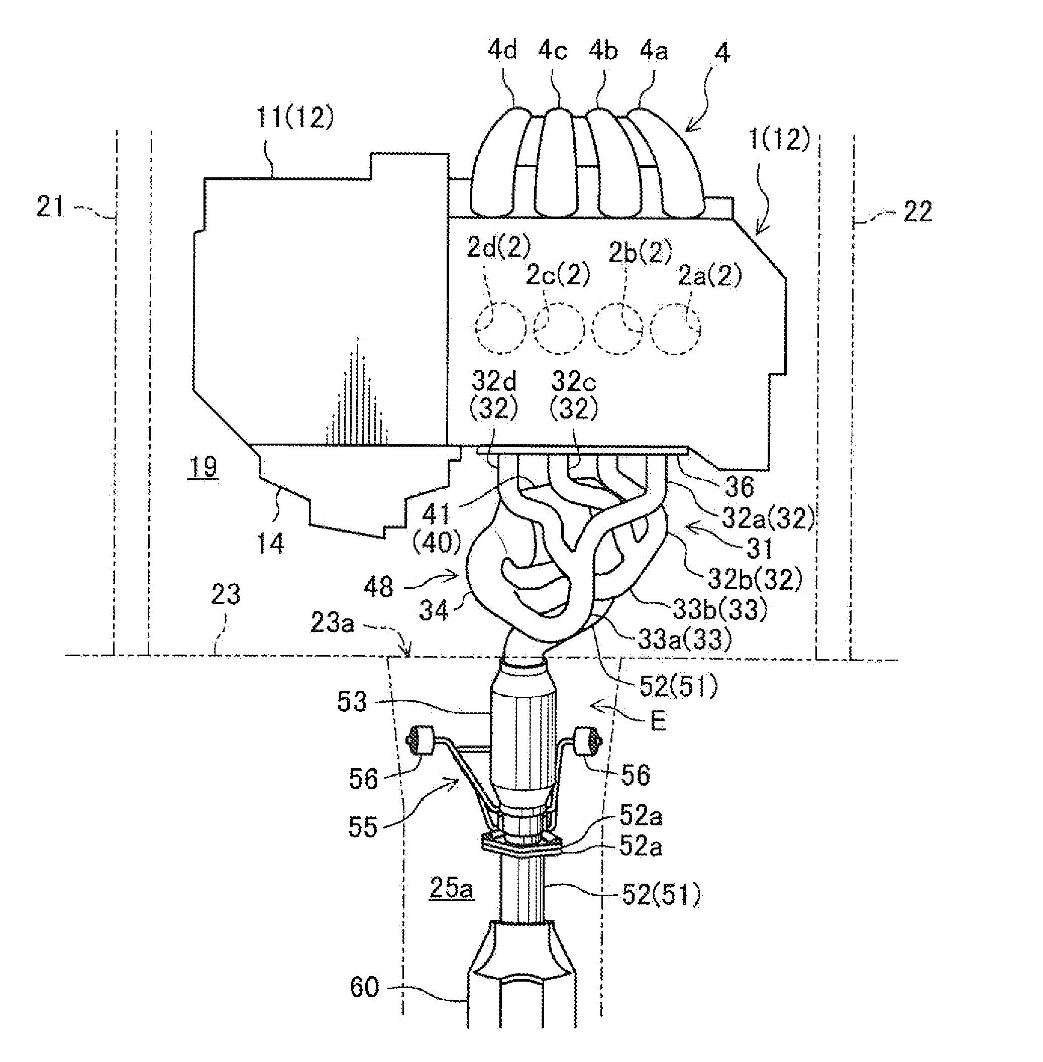
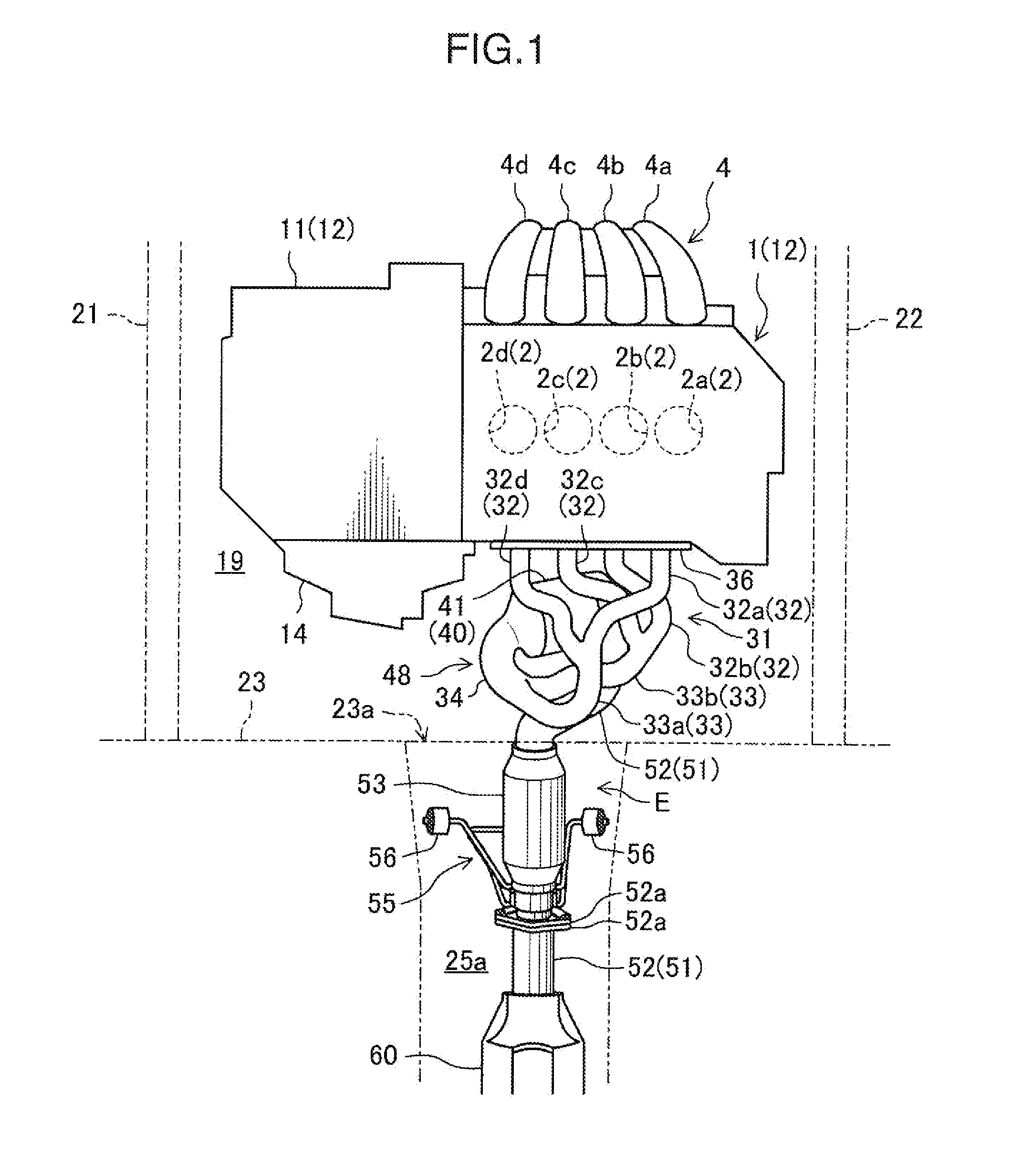
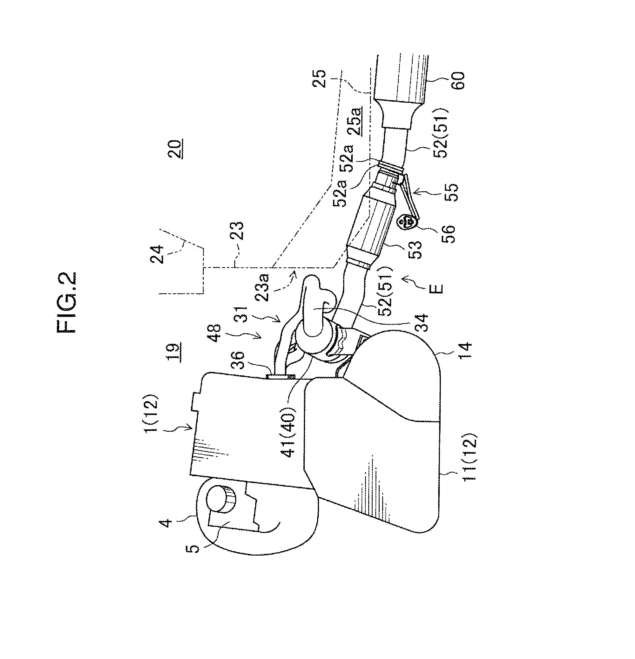
FIGS. 1 and 2 show an exhaust apparatus E according to a first embodiment of the present invention. The exhaust apparatus E is designed for a transverse engine 1. The engine 1 is an inline four-cylinder engine having four cylinders 2 arranged in a line, and transversely placed in an engine compartment 19 at a front of a vehicle to allow a cylinder arrangement direction to be oriented in a vehicle-widthwise direction (rightward-leftward direction in FIG. 1). In the following description, a right side of the vehicle which corresponds to a right side in FIG. 1 (reverse side of the drawing sheet of FIG. 2), a left side of the vehicle which corresponds to a left side in FIG. 1 (obverse side of the drawing sheet of FIG. 2), a front side of the vehicle which corresponds to an upper side in FIG. 1 (left side in FIG. 2), and a rear side of the vehicle which corresponds to a lower side in FIG. 1 (right side in FIG. 2), will be referred to respectively as “vehicle-right side”, “vehicle-left si...

second embodiment

FIGS. 6 to 8 show an exhaust apparatus E according to a second embodiment of the present invention, wherein a positional relationship between respective exhaust upstream ends of first and second intermediate collector pipe portions 33a, 33b (a merging position of first and fourth branch pipe portions 32a, 32d, and a merging position of second and third branch pipe portions 32b, 32c) is defined differently from that in the first embodiment.

Specifically, in the second embodiment, the exhaust upstream ends of the first and second intermediate collector pipe portions 33a, 33b are disposed at approximately the same position as that of a third fastening point 37c of a flange portion 36 in the vehicle-widthwise direction, and in offset relation to each other in an upward-downward direction. More specifically, the first branch pipe portion 32a and the fourth branch portion 32d are merged in the same manner as that in the first embodiment, whereas the second branch pipe portion 32b and the t...

third embodiment

FIGS. 9 to 11 show an exhaust apparatus E according to a third embodiment of the present invention, wherein a positional relationship between respective exhaust upstream ends of first and second intermediate collector pipe portions 33a, 33b (a merging position of first and fourth branch pipe portions 32a, 32d, and a merging position of second and third branch pipe portions 32b, 32c) is defined differently from those in the first and second embodiments.

Specifically, in the third embodiment, the exhaust upstream ends of the first and second intermediate collector pipe portions 33a, 33b are disposed at approximately the same position as that of a third fastening point 37c of a flange portion 36 in the vehicle-widthwise direction, as with the second embodiment. However, the exhaust upstream ends of the first and second intermediate collector pipe portions 33a, 33b are offset with respect to each other in the vehicle-longitudinal direction, instead of overlapping each other, in top plan ...


PUM


Abstract

An exhaust upstream section (48) of an exhaust apparatus (E) comprises a plurality of branch pipe portions (32), a plurality of intermediate collector pipe portions (33), a final collector pipe portion (34), and an exhaust gas-purifying unit (40). The exhaust gas-purifying unit (40) is disposed on a vehicle-rear side of an engine (1) to allow a gas passage thereinside to extend approximately in a vehicle-widthwise direction, in top plan view. Each of the plurality of intermediate collector pipe portions (33) curves to allow an exhaust downstream region of the intermediate collector pipe portion (33) to be oriented toward one side or the other side of the vehicle-widthwise direction, in top plan view, and the final collector pipe portion (34) curves to allow an exhaust downstream region of the final collector pipe portion (34) to be oriented toward a vehicle-front side, in top plan view. This makes it possible to compactly lay out the exhaust upstream section (48) in an engine compartment (19) without sacrificing a passenger compartment space, and quickly raise a temperature of a catalyst in an exhaust gas-purifying unit (40) during warm-up of the engine (1).

Description

BACKGROUND OF THE INVENTION1. Field of the InventionThe present invention relates to an exhaust apparatus for a transverse engine which is transversely placed in an engine compartment at a front of a vehicle to allow a cylinder arrangement direction to be oriented in a widthwise direction of the vehicle (vehicle-widthwise direction).2. Description of the Background ArtHeretofore, this type of transverse engine has been widely known. Typically, an exhaust apparatus for the transverse engine is disposed on a vehicle-rear side of the engine (see, for example, JP 2008-260472A, this document will hereinafter be referred to as “Patent Document 1”). The exhaust apparatus has a plurality of branch pipe portions each communicated with a respective one of a plurality of cylinders of the engine, wherein the branch pipe portions are merged to finally form a single collector pipe portion. Specifically, in the Patent Document 1, the entire cylinders (four cylinders) are divided into a plurality o...

Claims


Application Information

Patent Timeline
IPC IPC(8): F01N3/08
CPCF01N3/10F01N13/08F01N2340/04F01N13/1816F01N13/1822F01N13/10Y02A50/20
Inventor USHIJIMA, KENJIHASEGAWA, HIROKAZUNAKATANI, YASUSHIKITABATAKE, KEISHIKUSUNOKI, YASUSHIKAMO, TOSHIAKINAKAMURA, YOSHITAKAWATANABE, DAISUKESHIMOJI, HIROKINEGAMI, MASAMI
Owner MAZDA MOTOR CORP
Why Eureka
Try Eureka