Controller and control method for internal combustion engine

a control method and internal combustion engine technology, applied in the direction of electrical control, machine/engine, exhaust treatment electric control, etc., can solve the problems of increasing catalyst temperature, excessive catalyst temperature, and clogging of filter, etc., to reduce the effect of catalyst temperature increase, limiting the increase of catalyst temperature, and increasing catalyst temperatur

Active Publication Date: 2020-02-13
TOYOTA JIDOSHA KK
View PDF0 Cites 4 Cited by
  • Summary
  • Abstract
  • Description
  • Claims
  • Application Information

AI Technical Summary

Benefits of technology

[0008]In such a case, during the first period, rich air-fuel mixture is introduced into the three-way catalyst device, thereby increasing the catalyst temperature quickly. During the second period, which is subsequent to the first period, leaner air-fuel mixture than that during the first period is introduced into the three-way catalyst device, thereby limiting an increase in the catalyst temperature. This allows the temperature of the three-way catalyst device to increase quickly while limiting an excessive temperature increase.

Problems solved by technology

Thus, if the deposition is left, the deposited PM may eventually clog the filter.
During the execution of the catalyst temperature-increasing control, when the fuel concentration of the air-fuel mixture introduced into the three-way catalyst device is excessively high, the catalyst temperature increases excessively.
As a result, it takes time to complete the catalyst temperature-increasing control.
Thus, regardless of purposes, the above-described problem is common when the catalyst temperature-increasing control is performed by introducing unburned air-fuel mixture into the three-way catalyst device.
As a result, the temperature of the three-way catalyst device may increase insufficiently, thereby delaying completion of the temperature increase.

Method used


Image

  • Controller and control method for internal combustion engine
  • Controller and control method for internal combustion engine
  • Controller and control method for internal combustion engine

Examples


Embodiment Construction

[0025]This description provides a comprehensive understanding of the methods, apparatuses, and / or systems described. Modifications and equivalents of the methods, apparatuses, and / or systems described are apparent to one of ordinary skill in the art. Sequences of operations are exemplary, and may be changed as apparent to one of ordinary skill in the art, with the exception of operations necessarily occurring in a certain order. Descriptions of functions and constructions that are well known to one of ordinary skill in the art may be omitted.

[0026]Exemplary embodiments may have different forms, and are not limited to the examples described. However, the examples described are thorough and complete, and convey the full scope of the disclosure to one of ordinary skill in the art.

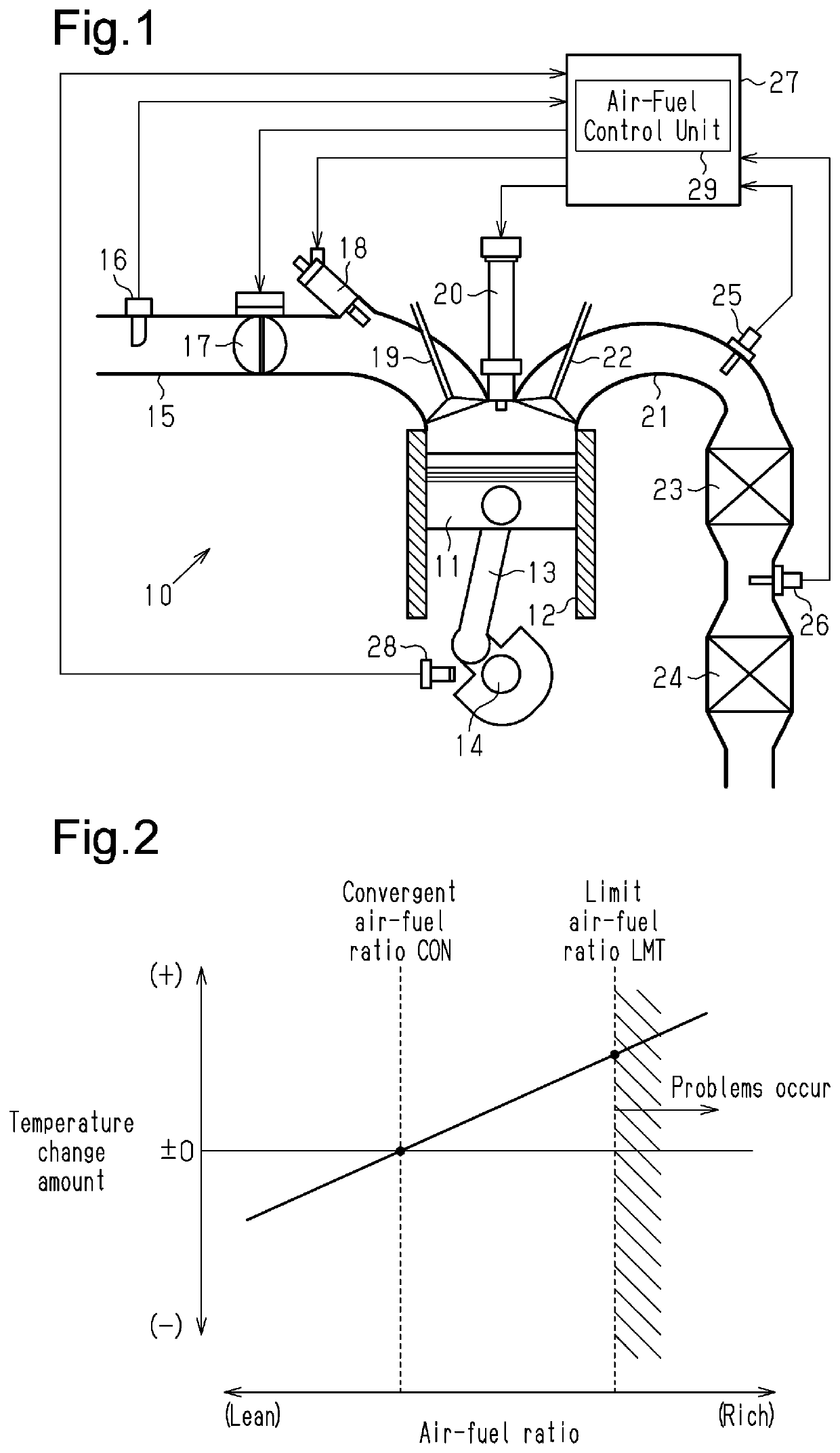
[0027]A controller for an internal combustion engine according to an embodiment will now be described in detail with reference to FIGS. 1 to 6.

[0028]FIG. 1 shows an internal combustion engine 10, to which the ...


PUM


Abstract

A controller is configured to control an internal combustion engine. The controller is configured to execute a catalyst temperature-increasing control of increasing a temperature of the three-way catalyst device by introducing air-fuel mixture, which contains the fuel injected by a fuel injection valve, into an exhaust passage without burning the air-fuel mixture in a cylinder. The controller includes an air-fuel ratio control unit configured to control an air-fuel ratio of the air-fuel mixture during the execution of the catalyst temperature-increasing control such that the air-fuel ratio becomes a richer air-fuel ratio during a first period from a beginning of the catalyst temperature-increasing control to a specified air-fuel ratio switching timing than during a second period from the air-fuel ratio switching timing to a completion of the catalyst temperature-increasing control.

Description

BACKGROUND1. Field[0001]The following description relates to a controller and a control method for an internal combustion engine applied to a spark-ignition internal combustion engine in which a three-way catalyst device is arranged in an exhaust passage.2. Description of Related Art[0002]A spark-ignition internal combustion engine performs combustion by igniting, with a spark of an ignition plug, the mixture of air and fuel introduced into a cylinder. The combustion of some of the fuel in the air-fuel mixture may be incomplete, thereby generating carbonaceous particulate matter (hereinafter referred to as PM).[0003]U.S. Patent Application Publication No. 2014 / 0041362 discloses an onboard spark-ignition internal combustion engine including a three-way catalyst device arranged in an exhaust passage and a PM-capturing filter arranged at the downstream side of the three-way catalyst device in the exhaust passage. In such an internal combustion engine, PM generated in the cylinder is ca...

Claims


Application Information

Patent Timeline
Patent Type & Authority Applications(United States)
IPC IPC(8): F02D41/02F01N3/035F01N11/00F01N3/10F02D41/38F01N3/025
CPCF01N2550/04F01N3/025F02D2041/389F01N3/101F01N11/00F02D41/025F02D41/38F01N3/035F02D41/029F01N3/023F01N3/2033F01N2430/06F01N2560/025F01N2560/06F01N2900/0422F01N2900/1402F01N2900/1602F01N2900/0418F01N13/009F01N3/0253F01N9/00F02P9/002
Inventor NOSE, YUKIIKEDA, YUTOMYOJO, KEIICHIANDO, HIROKAZU
Owner TOYOTA JIDOSHA KK
Why Eureka
Try Eureka