Method for controlling fuel reformer

a fuel reformer and fuel technology, applied in the field of fuel reformers, can solve the problems of limiting the use of hydrogen fuel cells, continuously supplied from outside, and a long time for heat supplied from external heating wires to be transferred to the inside of the laminated pellet type catalyst, so as to reduce the supply amount of fuel and air, and the catalyst temperature is drastically increased

Active Publication Date: 2014-03-20
AGENCY FOR DEFENSE DEV
View PDF3 Cites 5 Cited by
  • Summary
  • Abstract
  • Description
  • Claims
  • Application Information

AI Technical Summary

Benefits of technology

[0016]To achieve these and other advantages and in accordance with the purpose of this specification, as embodied and broadly described herein, there is provided a method for controlling a fuel reformer, the method comprising: heating a catalyst of the fuel reformer by operating an electric heater formed to enclose the catalyst; supplying fuel and air to the catalyst under a condition of complete combustion; flame-combusting the fuel by igniting an ignition plug installed near a rear end of the catalyst; and shifting the position of the flame combustion to inside of the catalyst, by reducing a supply amount of the fuel and the air, such that temperature of the catalyst is drastically increased.

Problems solved by technology

However, there is a limitation in adopting fuel cells using hydrogen in the current situation where hydrogen supply is not sufficient.
However, such method is disadvantageous in that heat should be continuously supplied from outside.
Accordingly, it takes a lot of time for heat supplied from external heating wires to be transferred up to inside of the laminated pellet type catalyst.
However, it is difficult to anticipate rapid heat transfer, because an insulator is disposed between the monolith catalyst and the case in order to fix the monolith catalyst into the case.
However, the inner structure of the reactor may become complicated and the fabrication costs may be increased, because the heating wires should be inserted into the reactor through the case.
Further, in case of using the heating wires, an excessive amount of electric energy is required.
However, such method has the following problems.
Firstly, the catalyst may be drastically thermally-deteriorated due to thermal impacts.
Further, soot may be absorbed to the surface of the catalyst when incomplete combustion occurs.
This may degrade performance of the catalyst.

Method used


Image

  • Method for controlling fuel reformer
  • Method for controlling fuel reformer
  • Method for controlling fuel reformer

Examples


Embodiment Construction

[0031]Description will now be given in detail of the exemplary embodiments, with reference to the accompanying drawings. For the sake of brief description with reference to the drawings, the same or equivalent components will be provided with the same reference numbers, and description thereof will not be repeated.

[0032]Hereinafter, a method for controlling a fuel reformer according to the present invention will be explained in more detail with reference to the attached drawings.

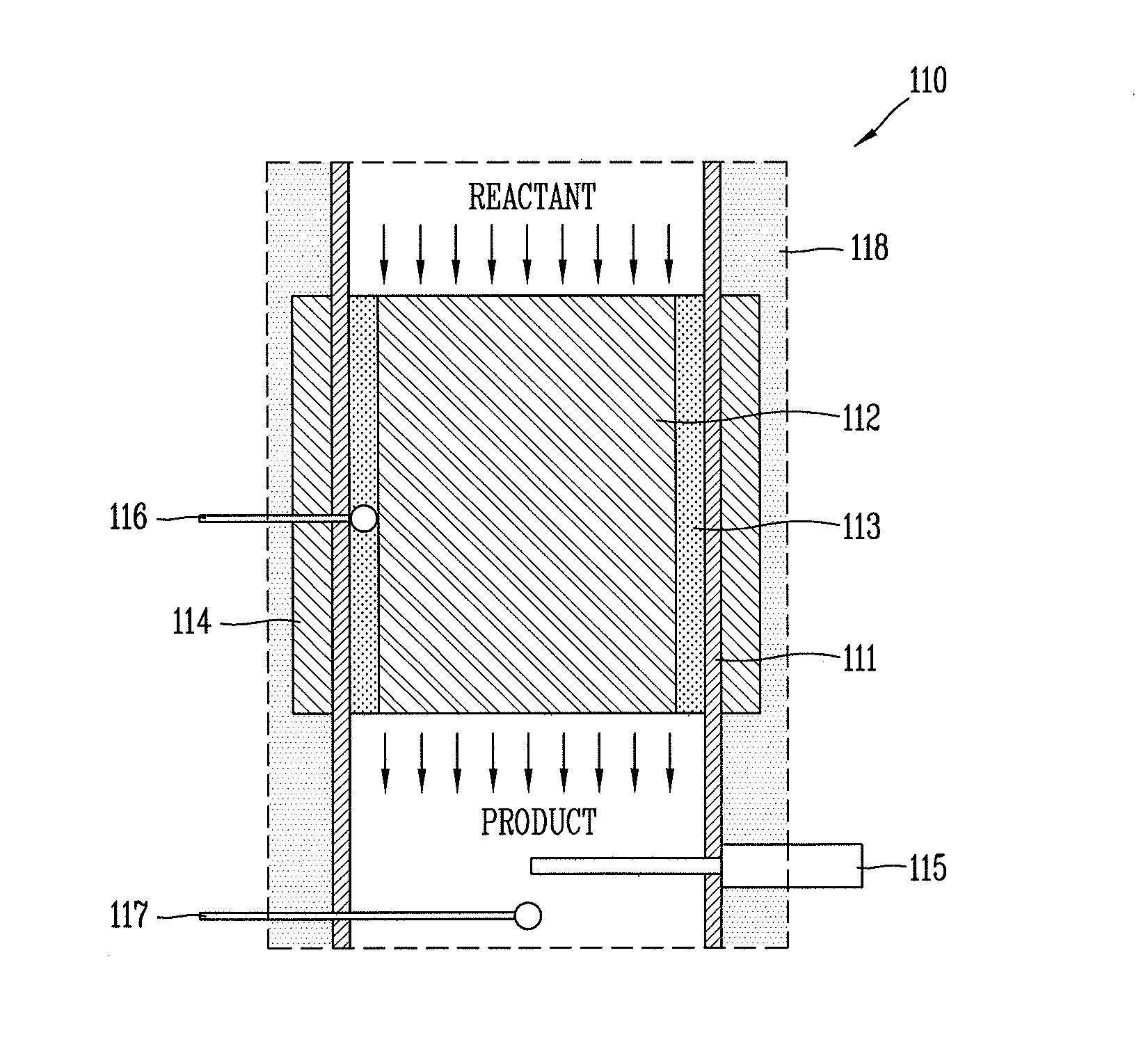
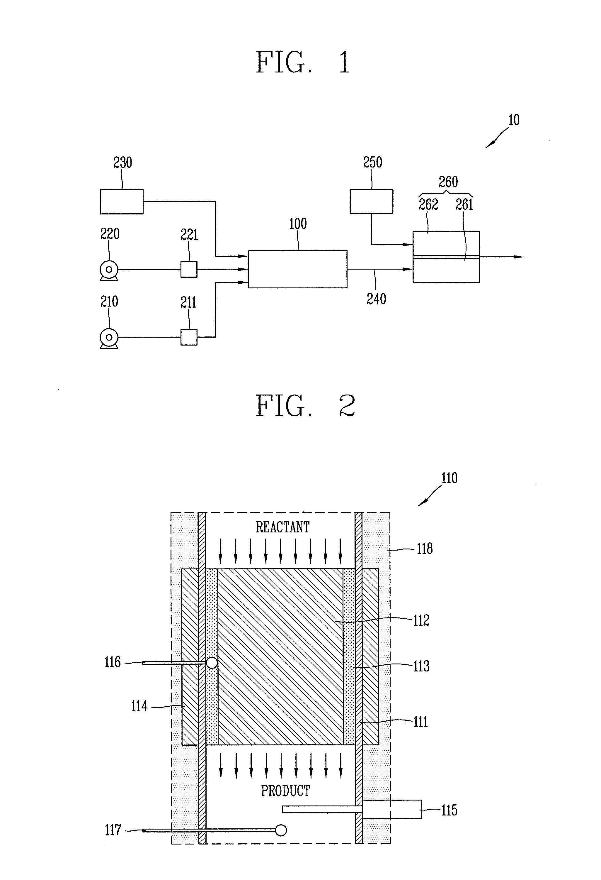
[0033]FIG. 1 is a conceptual view illustrating a fuel cell system 10 according to an embodiment of the present invention.

[0034]A fuel reformer 100 is connected to each of a fuel pump 210 configured to supply fuel for reaction, a water pump 220 configured to supply water for reaction, and a blower 230 configured to supply air for reaction. Fuel and water, which are supplied from the fuel pump 210 and the water pump 220, respectively, are evaporated through evaporators 211 and 221, to thus be supplied to the f...


PUM

PropertyMeasurementUnit
temperatureaaaaaaaaaa

Abstract

A method for controlling a fuel reformer, capable of generating hydrogen by reforming fuel, comprises: heating a catalyst of the fuel reformer by operating an electric heater formed to enclose the catalyst; supplying fuel and air to the catalyst under a condition of complete combustion; flame-combusting the fuel by igniting an ignition plug installed near a rear end of the catalyst; and shifting the position of the flame combustion to inside of the catalyst, by reducing a supply amount of the fuel and the air, such that temperature of the catalyst is drastically increased.

Description

CROSS-REFERENCE TO RELATED APPLICATIONS[0001]Pursuant to 35 U.S.C. §119(a), this application claims the benefit of earlier filing date and right of priority to Korean Application No. 10-2012-0103440, filed on Sep. 18, 2012, the contents of which is incorporated by reference herein in its entirety.BACKGROUND OF THE DISCLOSURE[0002]1. Field of the Disclosure[0003]The present disclosure relates to a fuel reformer, and particularly, to a method for controlling a fuel reformer, which is capable of allowing a catalyst of the fuel reformer to reach a starting temperature within a shortest time.[0004]2. Background of the Disclosure[0005]A fuel cell indicates an energy conversion apparatus capable of directly converting chemical energy into electric energy, by a chemical reaction between fuel (hydrogen) and an oxidant (oxygen), through a reverse reaction of a water electrolysis. Hydrogen gas supplied to an anode of the fuel cell is divided into hydrogen ions and electrons through a catalyst....

Claims


Application Information

Patent Timeline
Patent Type & Authority Applications(United States)
IPC IPC(8): C01B3/02
CPCC01B3/02C01B3/38C01B3/382C01B2203/0233C01B2203/0244C01B2203/0261C01B2203/0283C01B2203/044C01B2203/066C01B2203/0816C01B2203/085C01B2203/0866C01B2203/1005C01B2203/1023C01B2203/1288C01B2203/1604C01B2203/1619C01B2203/169C01B2203/1695H01M8/0618Y02E60/50C01B3/26H01M8/06H01M8/10
Inventor JI, HYUN JINHA, SANG HYEONCHO, SUNG BAEK
Owner AGENCY FOR DEFENSE DEV
Why Eureka
Try Eureka