Turbocharger

a turbocharger and exhaust gas technology, applied in combination engines, machines/engines, mechanical apparatus, etc., can solve the problems of low temperature of exhaust gas flowing through bypass passages, increase in boost pressure, and inability of purification systems to perform full purification functions, etc., to achieve the effect of quick raising the temperature of catalys

Inactive Publication Date: 2015-09-24
IHI CORP
View PDF3 Cites 0 Cited by
  • Summary
  • Abstract
  • Description
  • Claims
  • Application Information

AI Technical Summary

Benefits of technology

[0012]According to the present disclosure, it is possible to provide a turbocharger which is capable of quickly raising the temperature of a catalyst by use of an exhaust gas discharged from a discharge passage.

Problems solved by technology

If, however, the energy of the exhaust gas is too large, there is a case where the boost pressure increases too much.
At a time of engine start, however, the temperature of a catalyst in the purification system does not rise, and the purification system accordingly cannot perform its purification function fully.
Thus, the temperature of the exhaust gas flowing through the bypass passage becomes lower, and the rise in the temperature of the catalyst is accordingly delayed.

Method used


Image

  • Turbocharger
  • Turbocharger
  • Turbocharger

Examples


Embodiment Construction

[0018]Referring to the accompanying drawings, detailed description will be hereinbelow provided for a preferred embodiment of the present disclosure. Dimensions, materials, concrete numerical values and the like in the embodiment are shown just as examples for the purpose of making the present disclosure easy to understand, and do not limit the present disclosure unless otherwise indicated. It should be noted that throughout the description and the drawings, components having virtually the same functions and configurations are denoted with the same reference signs, and duplicated explanations for such components will be omitted. In addition, components having nothing direct to do with the present disclosure are omitted from the drawings.

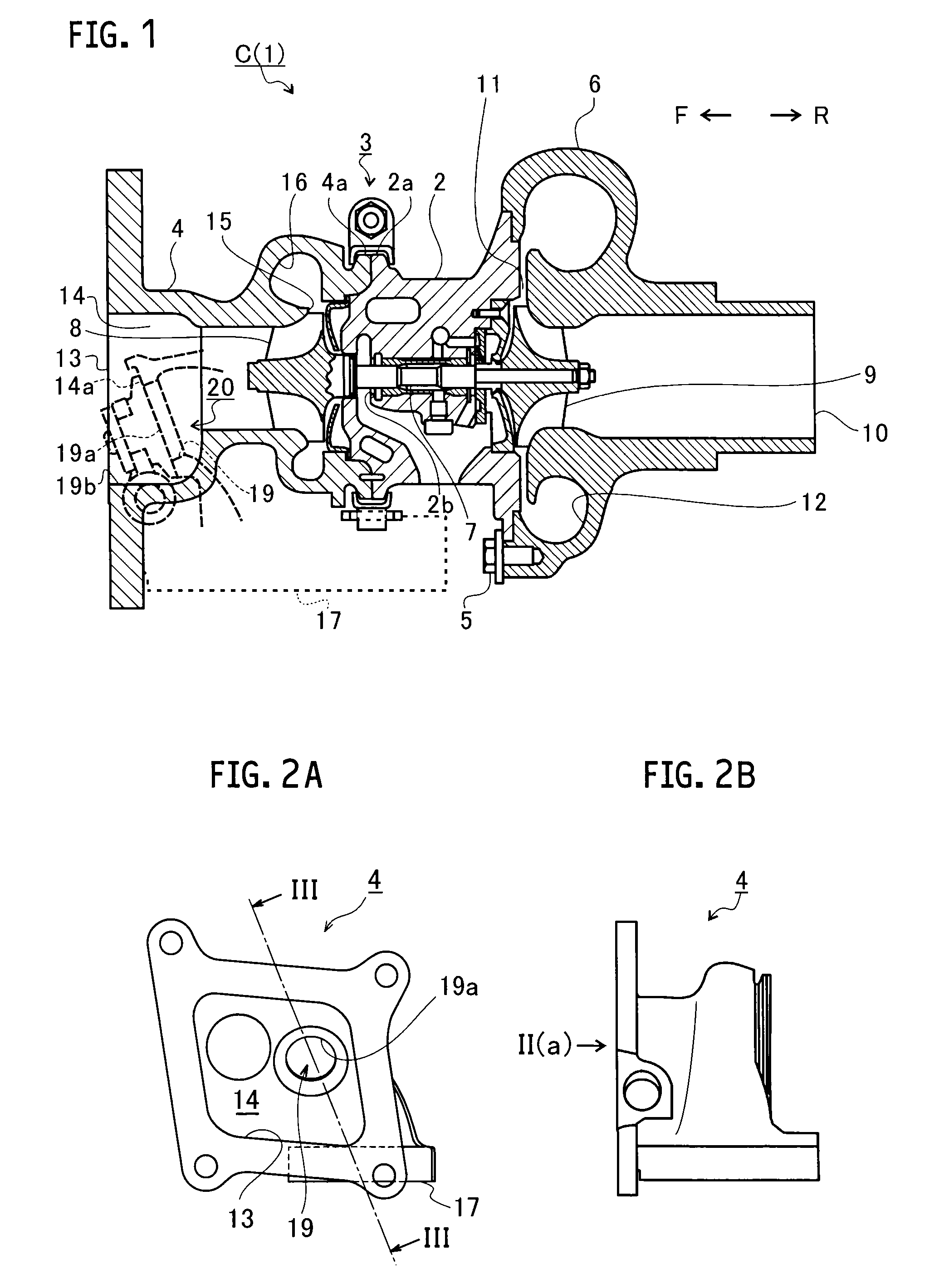
[0019]FIG. 1 is a schematic cross-sectional view of a turbocharger C. The following descriptions will be given with arrows F, R directions in FIG. 1 pointing the front and rear of the turbocharger C, respectively. As shown in FIG. 1, the turbocharger...


PUM


Abstract

A turbocharger includes: inlet and discharge passages to guide a fluid to a turbine wheel and discharge the fluid therefrom; a bypass passage communicating between the inlet passage and the discharge passage to bypassing the turbine wheel; a seat surface facing the discharge passage, in which an end of the bypass passage opens; and a mechanism to open and close the end of the bypass passage. The mechanism includes: a stem turnably supported by the turbine housing; and a valve body to open and close the end of the bypass passage. The seat surface tilts from a plane perpendicular to a turbine shaft in a way that a side on which the stem is disposed is located farther from a discharge port of the discharge passage than an opposite side of the end of the bypass passage from the side on which the stem is disposed.

Description

CROSS REFERENCE TO RELATED APPLICATIONS[0001]This application is a continuation application of International Application No. PCT / JP2013 / 084218, filed on Dec. 20, 2013, which claims priority to Japanese Patent Application No. 2013-002838, filed on Jan. 10, 2013, the entire contents of which are incorporated by references herein.BACKGROUND[0002]1. Field[0003]The present disclosure relates to a turbocharger including a bypass passage configured to communicate between upstream and downstream sides of a turbine wheel while bypassing the turbine wheel.[0004]2. Background Art—Description of the Related Art[0005]A turbocharger raises a boost pressure to an engine by: rotating a turbine wheel using energy of an exhaust gas; and rotating a compressor wheel using the rotation of the turbine wheel via a turbine shaft. After rotating the turbine wheel, the exhaust gas is discharged to outside a turbine housing from a discharge passage provided in the turbine housing. If, however, the energy of t...

Claims


Application Information

Patent Timeline
Patent Type & Authority Applications(United States)
IPC IPC(8): F02B37/18
CPCF02B37/186Y02T10/12
Inventor IWATA, KAZUAKIMORI, ATSUSHIISONO, YUUSUKE
Owner IHI CORP
Why Eureka
Try Eureka