Control device and control method for hybrid vehicle

a control device and hybrid technology, applied in the direction of electrical control, exhaust treatment electric control, engine starters, etc., can solve the problems of deteriorating the properties of the exhaust gas of the vehicle, inhibiting the divergence between the requested the actual output of the hybrid system, and high upper limit system output, so as to reduce the temperature of the catalyst, limit the deterioration of the fuel efficiency of the internal combustion engine, and limit the deterioration of the properties of the exhaust gas

Active Publication Date: 2020-10-22
TOYOTA JIDOSHA KK
View PDF0 Cites 0 Cited by
  • Summary
  • Abstract
  • Description
  • Claims
  • Application Information

AI Technical Summary

Benefits of technology

[0014]According to the above configuration, the catalyst temperature is increased without starting the engine operation by executing the catalyst temperature increase process. Increasing the upper limit engine output by increasing the catalyst temperature enables making the upper limit system output to be higher than the startup determination output. Even in this case, when the upper limit motor output is decreased due to decrease in the charge amount, the upper limit system output becomes lower than or equal to the startup determination output again. Thus, the engine operation is started by the execution of the shifting process. That is, according to the above configuration, starting of the engine operation is delayed by increasing the upper limit engine output by execution of the catalyst temperature increase process. In other words, the vehicle is allowed to keep running in the first drive mode, which limits the deterioration in the fuel efficiency of the internal combustion engine.
[0015]Furthermore, the lower the temperature of the cylinder block and the cylinder head constituting the internal combustion engine is, the more likely it is that there will be a greater amount of the unburnt fuel contained in the exhaust gas discharged from the cylinders of the internal combustion engine to the exhaust passage. The lower the temperature of the liquid that circulates in the internal combustion engine is, the lower the temperature of the cylinder block and the cylinder head becomes. Thus, as Example 3, in the control device for a hybrid vehicle as described in the above aspects, the second upper limit calculation section may be configured to increase the upper limit engine output as a temperature of liquid that circulates in the internal combustion engine is increased.
[0016]According to the above configuration, the upper limit engine output is decreased as the temperature of the liquid is decreased. Since the upper limit system output is decreased as the upper limit engine output is decreased, the upper limit system output becomes lower than or equal to the startup determination output at an earlier stage accordingly. That is, the shifting process is executed at an early stage. That is, the engine operation is started at an early stage. This limits an output that exceeds the upper limit engine output from being requested from the internal combustion engine and limits the deterioration in the properties of the exhaust gas.

Problems solved by technology

This deteriorates the properties of the exhaust gas of the vehicle.
The upper limit system output is high since the upper limit motor output is high when the charge amount is great even if the first drive mode is selected and the catalyst temperature is out of the activation temperature range.
Thus, when the charge amount is great, the divergence between the requested output of the hybrid system and the actual output of the hybrid system is inhibited.
Thus, at that point in time, the upper limit motor output is still high.
Consequently, the requested output of the hybrid system is still inhibited from exceeding the upper limit system output.
As a result, the high output that exceeds the upper limit engine output is inhibited from being requested from the internal combustion engine.
In other words, the vehicle is allowed to keep running in the first drive mode, which limits the deterioration in the fuel efficiency of the internal combustion engine.
Furthermore, the lower the temperature of the cylinder block and the cylinder head constituting the internal combustion engine is, the more likely it is that there will be a greater amount of the unburnt fuel contained in the exhaust gas discharged from the cylinders of the internal combustion engine to the exhaust passage.
This limits an output that exceeds the upper limit engine output from being requested from the internal combustion engine and limits the deterioration in the properties of the exhaust gas.
That is, the vehicle is allowed to keep running in the first drive mode, which limits the deterioration in the fuel efficiency of the internal combustion engine.

Method used


Image

  • Control device and control method for hybrid vehicle
  • Control device and control method for hybrid vehicle
  • Control device and control method for hybrid vehicle

Examples


first embodiment

[0033]A control device 80 for a hybrid vehicle according to a first embodiment of the present disclosure will be described with reference to FIGS. 1 to 5.

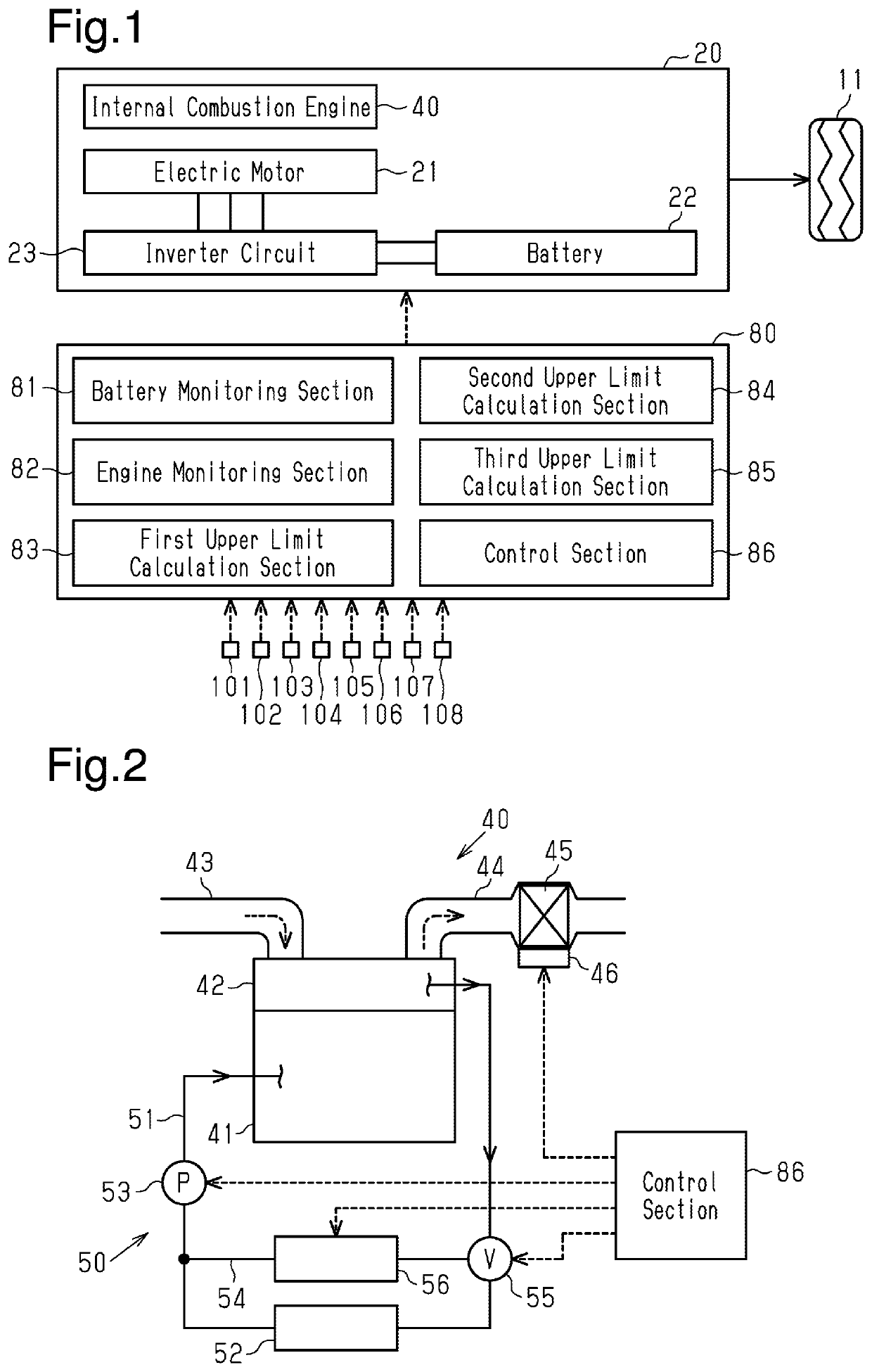
[0034]FIG. 1 shows the control device 80 of the present embodiment and a hybrid system 20 controlled by the control device 80. A vehicle equipped with the hybrid system 20 is a plug-in hybrid vehicle that allows a battery 22 to be charged by a power supply from outside the vehicle.

[0035]The hybrid system 20 includes an electric motor 21 and an internal combustion engine 40 as power sources of the vehicle. That is, the hybrid system 20 is capable of both inputting the output torque of the electric motor 21 to wheels 11 and inputting the output torque of the internal combustion engine 40 to the wheels 11. To cause the electric motor 21 to function as a power source of the vehicle, a direct-current voltage of the battery 22 is converted to an alternating-current voltage by an inverter circuit 23, and the alternating-current voltage is...

second embodiment

[0074]A control device for a hybrid vehicle according to a second embodiment of the present disclosure will now be described with reference to FIG. 6. In the second embodiment, the structure of the engine heating section differs from that of the first embodiment. The differences between the first embodiment and the second embodiment will mainly be discussed in the following description. The same or equivalent components as the first embodiment are given the same reference numerals, and redundant descriptions will be omitted.

[0075]FIG. 6 illustrates the coolant circulation device 50 for the internal combustion engine 40 and a motor cooling device 200. The motor cooling device 200 is a device that circulates the coolant to cool the battery 22 and the inverter circuit 23. The motor cooling device 200 includes a motor coolant circuit 201 and a motor coolant pump 202, which is operated to circulate the coolant in the motor coolant circuit 201 as shown by the arrows in FIG. 6.

[0076]In the...


PUM


Abstract

A control device for a hybrid vehicle is provided. When a first drive mode is selected as the drive mode of the hybrid vehicle, a control section shifts the drive mode to a second drive mode when a charge amount of a battery for an electric motor becomes smaller than or equal to a determination charge amount. The first drive mode operates the electric motor while an internal combustion engine is stopped. The second drive mode permits the operation of the internal combustion engine. The control section executes a shifting process when the upper limit system output is lower than or equal to a startup determination output even though the charge amount of the battery is greater than the determination charge amount. The shifting process shifts the drive mode to the second drive mode to start the internal combustion engine.

Description

BACKGROUND1. Field[0001]The present disclosure relates to a control device and a control method for a hybrid vehicle. The control device and the control method control a hybrid system that includes an internal combustion engine and an electric motor as vehicle power sources.2. Description of Related Art[0002]Japanese Laid-Open Patent Publication No. 2008-106675 discloses an example of a control device that uses a first drive mode and a second drive mode depending on the condition. In the first drive mode, the operation of the internal combustion engine is stopped while operating the electric motor to drive the vehicle. In the second drive mode, the internal combustion engine is operated to drive the vehicle. According to such a control device, under the condition in which the first drive mode is selected as the drive mode, the charge amount of a battery for the electric motor decreases. When the charge amount becomes smaller than or equal to a determination charge amount, the drive ...

Claims


Application Information

Patent Timeline
Patent Type & Authority Applications(United States)
IPC IPC(8): B60W20/40B60W10/10B60W10/06B60W10/08B60W20/10
CPCB60W10/10B60W20/40B60W2510/244B60W2510/0666B60W10/08B60W2510/068B60W2510/085B60W10/06B60W20/10B60W10/26B60W20/20B60W20/16B60W2510/246B60W2710/086B60W2710/0677B60W20/13B60W2530/12B60Y2300/474B60W20/11B60W2710/0688B60W30/194F02N11/0818F02D41/0255F01N3/2006F02N2200/061F02N2200/023F01N2900/1626F01N2900/1602F01N2590/11F01N2900/08F01N2900/104F01N2900/10F01N9/00Y02T10/12Y02T10/70Y02T10/72Y02T10/62
Inventor MORIYAMA, YOHEINAKAYAMA, SHIGEKITSUZUKI, IKUMA
Owner TOYOTA JIDOSHA KK
Why Eureka
Try Eureka