Exhaust Heat Recovery System of Vehicle and Method Thereof

a technology of exhaust heat recovery and vehicle, which is applied in the direction of engines, mechanical equipment, machines/engines, etc., can solve the problems of increasing the manufacturing cost of vehicles, and achieve the effects of shortening the warm-up time of engines, reducing fuel consumption, and quick raising of engine oil temperatur

Inactive Publication Date: 2011-06-02
HYUNDAI MOTOR CO LTD +1
View PDF7 Cites 29 Cited by
  • Summary
  • Abstract
  • Description
  • Claims
  • Application Information

AI Technical Summary

Benefits of technology

[0019]In the present invention as stated above, the coolant is actively controlled in an early stage of starting of the engine so as to shorten a warm-up time of the engine such that fuel consumption is reduced and exhaust gas is stabilized.
[0020]In the present invention, stable exhaust gas can be secured without adding a catalyst, the temperature of engine oil can be quickly raised, oil friction is rapidly decreased, and abrasion of components is minimized such that durability thereof is improved.

Problems solved by technology

When a catalyst loading amount is increased and an EGR cooler capacity becomes larger so as to satisfy exhaust gas regulations, the manufacturing cost of a vehicle is also increased.

Method used


Image

  • Exhaust Heat Recovery System of Vehicle and Method Thereof
  • Exhaust Heat Recovery System of Vehicle and Method Thereof
  • Exhaust Heat Recovery System of Vehicle and Method Thereof

Examples


Embodiment Construction

[0026]Reference will now be made in detail to various embodiments of the present invention(s), examples of which are illustrated in the accompanying drawings and described below. While the invention(s) will be described in conjunction with exemplary embodiments, it will be understood that present description is not intended to limit the invention(s) to those exemplary embodiments. On the contrary, the invention(s) is / are intended to cover not only the exemplary embodiments, but also various alternatives, modifications, equivalents and other embodiments, which may be included within the spirit and scope of the invention as defined by the appended claims.

[0027]In the following detailed description, only certain exemplary embodiments of the present invention have been shown and described, simply by way of illustration.

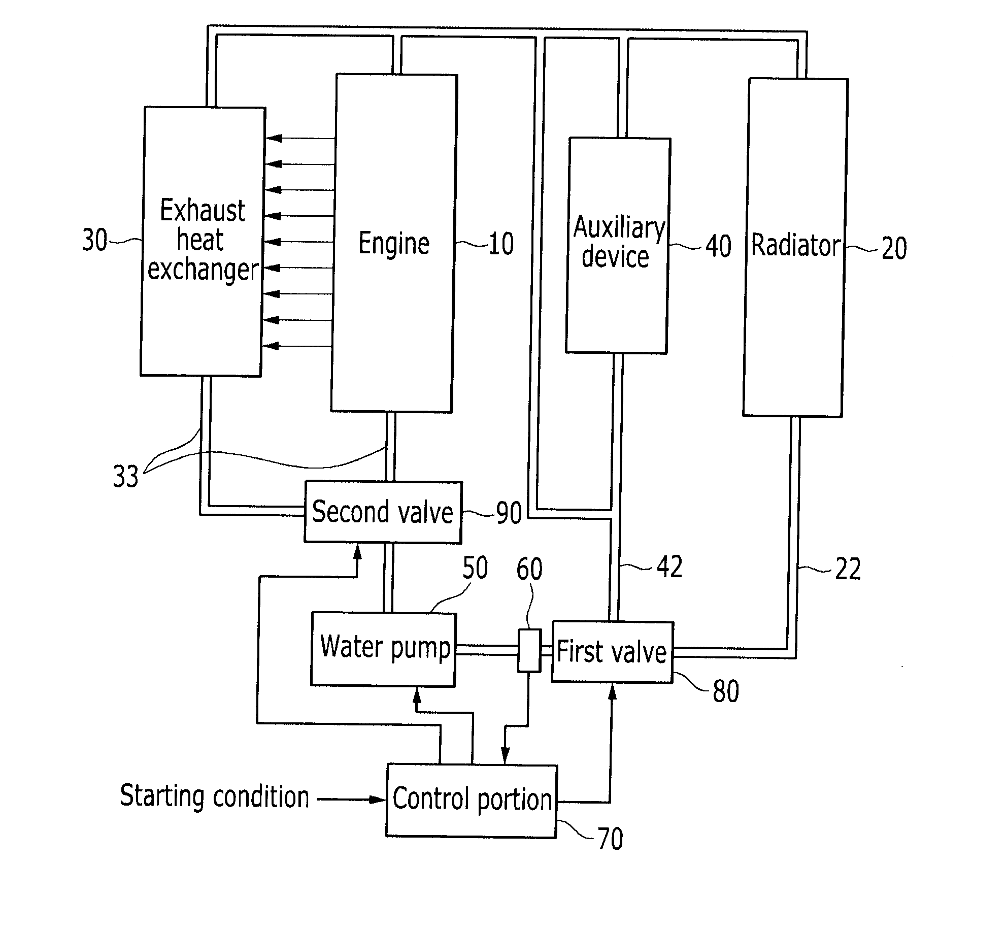
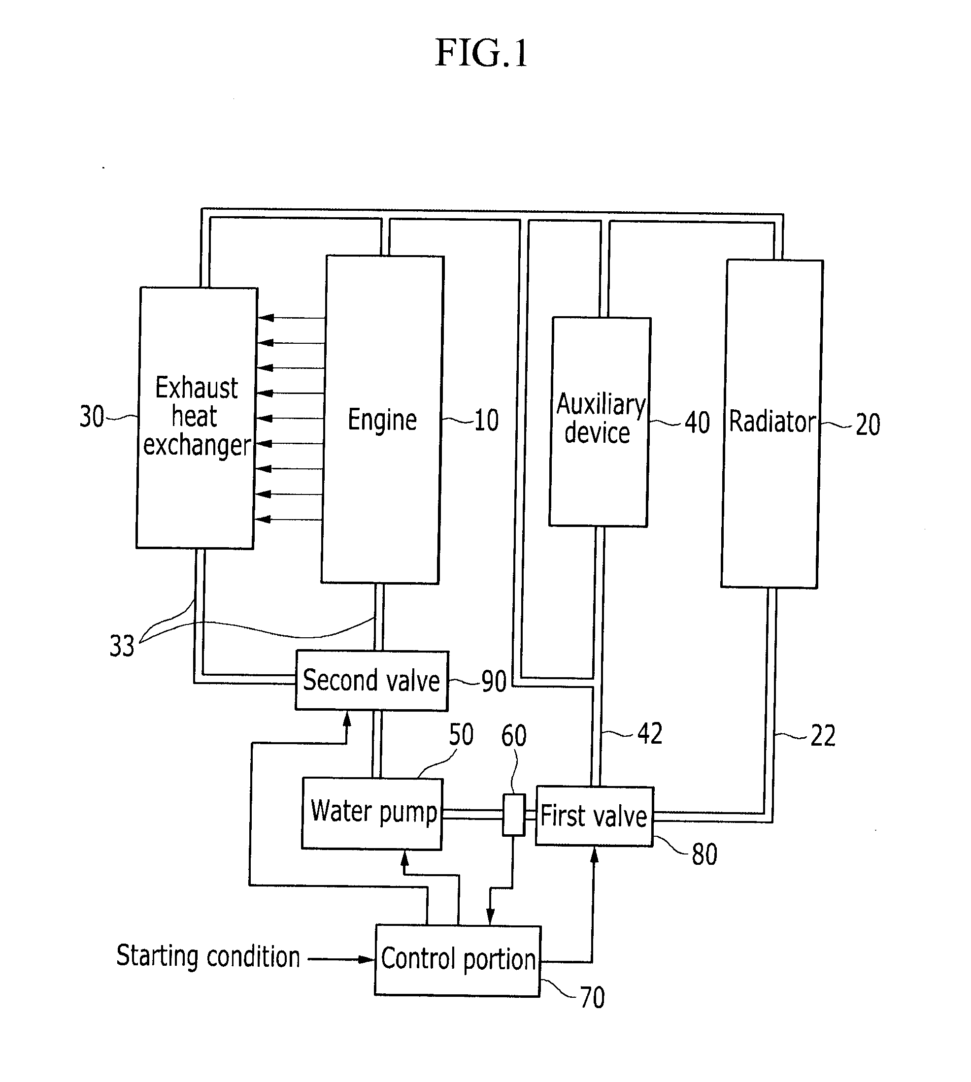
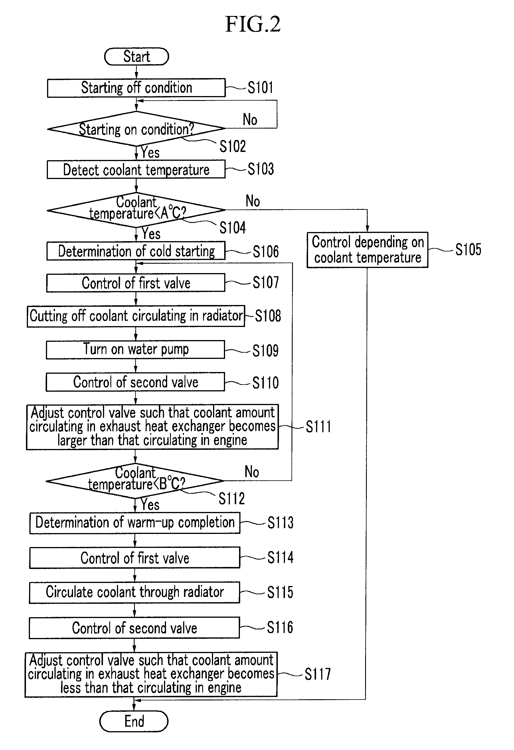
[0028]FIG. 1 schematically shows an exhaust heat recovery device of a vehicle according to an exemplary embodiment of the present invention exemplary embodiment.

[0029]The...


PUM


Abstract

An exhaust heat recovery device may include a radiator disposed at a main line and through which hot coolant circulates, an exhaust heat exchanger transferring exhaust heat of an engine to coolant, a first valve selectively circulating the coolant to the main line or a bypass line, a water pump connected to the first valve and circulating the coolant, a coolant temperature sensor detecting temperature of the coolant, a second valve connected to the water pump and disposed at a distributing line to distribute the coolant supplied by the water pump to the engine and the exhaust heat exchanger, and a control portion that controls the first and second valves depending on the temperature of the coolant so as to adjust coolant amount circulating in the engine and the exhaust heat exchanger and coolant amount circulating in the radiator and the bypass line.

Description

CROSS-REFERENCE TO RELATED APPLICATION[0001]The present application claims priority to Korean Patent Application No. 10-2009-0118730 filed in the Korean Intellectual Property Office on Dec. 2, 2009, the entire contents of which is incorporated herein for all purposes by this reference.BACKGROUND OF THE INVENTION[0002]1. Field of the Invention[0003]The present invention relates to an exhaust heat recovery device of a vehicle. More particularly, the present invention relates to an exhaust heat recovery device of a vehicle that recovers heat of exhaust gas to decrease fuel consumption, and a method thereof.[0004]2. Description of Related Art[0005]In general, vehicle makers are researching ways to decrease exhaust gas and fuel consumption.[0006]When a catalyst loading amount is increased and an EGR cooler capacity becomes larger so as to satisfy exhaust gas regulations, the manufacturing cost of a vehicle is also increased.[0007]A variable water pump prevents unnecessary cooling such th...

Claims


Application Information

Patent Timeline
Patent Type & Authority Applications(United States)
IPC IPC(8): F01P7/14
CPCF01N5/02F01P7/16Y02T10/16F01P2060/08F01P7/165Y02T10/12F02G5/02
Inventor HWANG, SOON HYONLEE, BONG SANG
Owner HYUNDAI MOTOR CO LTD
Why Eureka
Try Eureka