Apparatus And System For A Battery Pack Assembly Used During Mechanical Ventilation

a battery pack and mechanical ventilation technology, applied in the field of ventilation, can solve problems such as risk of operation

Active Publication Date: 2011-06-02
TYCO HEALTHCARE GRP LP
View PDF3 Cites 131 Cited by
  • Summary
  • Abstract
  • Description
  • Claims
  • Application Information

AI Technical Summary

Problems solved by technology

One problem with powering a transportable ventilator is monitoring the charge on batteries used as a power source when the ventilator is mobile.
Removing a battery pack when the ventilator is relying on battery power can risk the operation of the ventilator as well as the ultimate health of the ventilatory patient.

Method used


Image

  • Apparatus And System For A Battery Pack Assembly Used During Mechanical Ventilation
  • Apparatus And System For A Battery Pack Assembly Used During Mechanical Ventilation
  • Apparatus And System For A Battery Pack Assembly Used During Mechanical Ventilation

Examples


Embodiment Construction

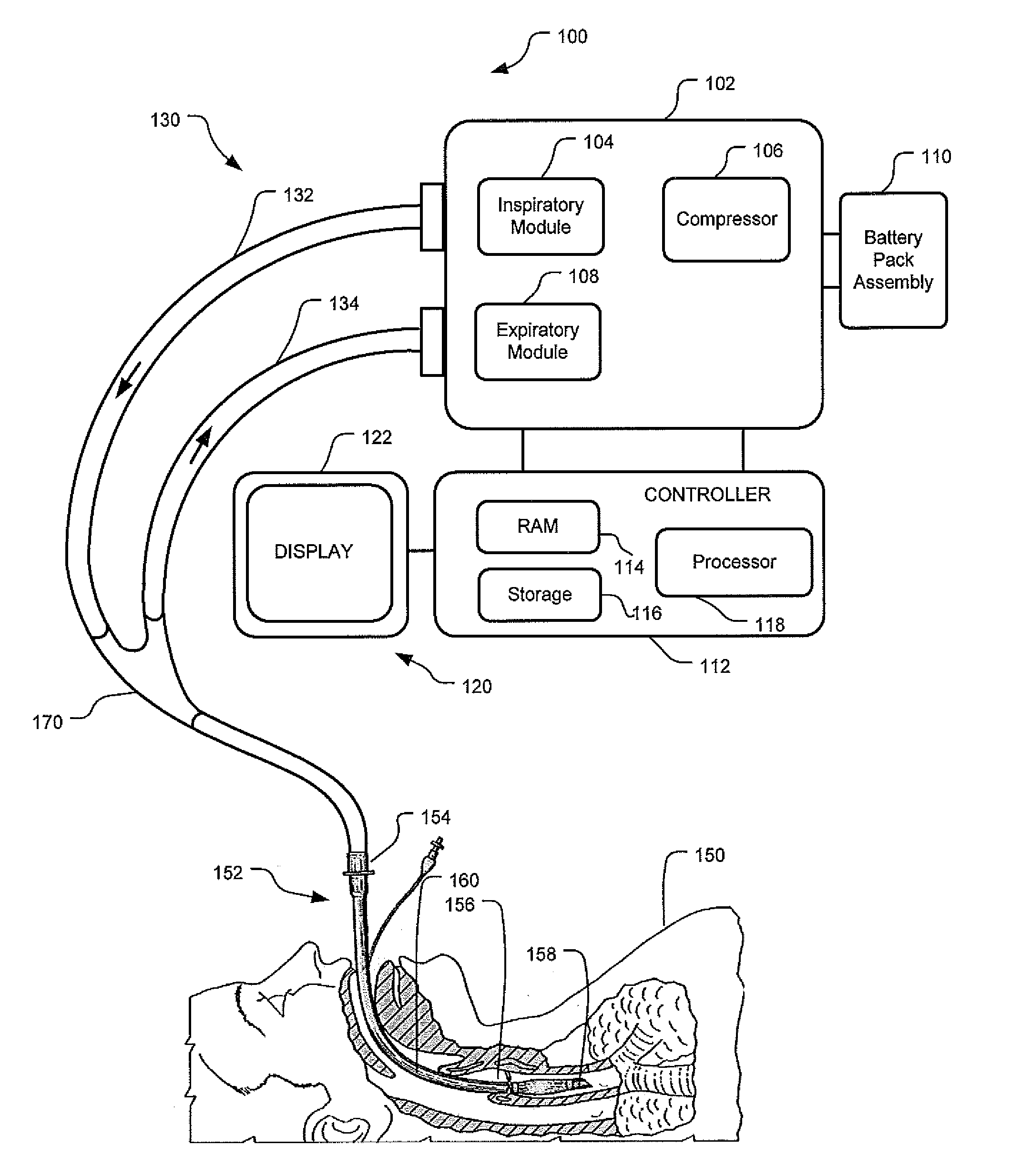
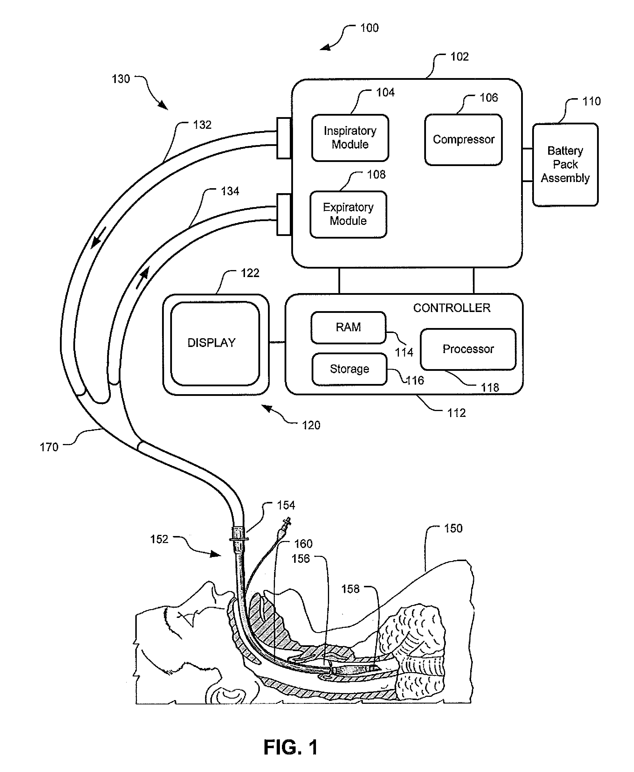
[0018]Although the techniques introduced above and discussed in detail below may be implemented for a variety of devices, the present disclosure will discuss the implementation of these techniques for use in a mechanical ventilator system. The reader will understand that the battery pack assembly could be implemented in other technologies providing power by both one or more battery pack assemblies and a separate power supply.

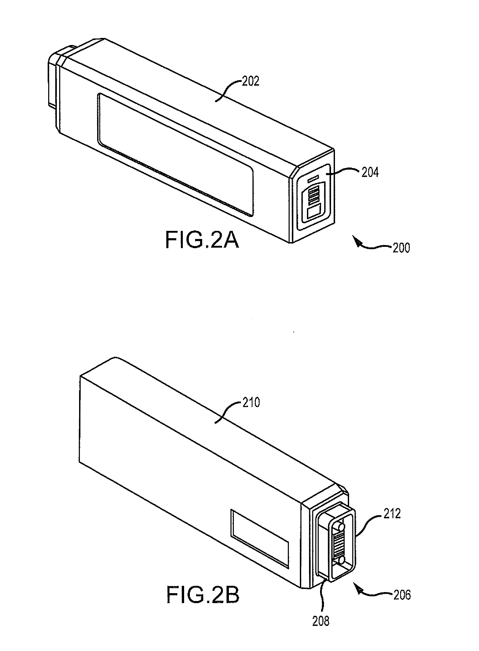
[0019]The disclosure describes methods and apparatus for indicating battery cell status on the exterior of a battery pack assembly. The disclosure further describes a battery pack assembly used during mechanical ventilation. The disclosure discusses scenarios when the battery pack assembly is “in use” and when the battery pack assembly is “not in use.” Describing a battery pack assembly as “in use” means that the battery pack assembly inserted into a host is the source of power for the host, such as a ventilator. Describing a battery pack assembly as “not in use...


PUM

PropertyMeasurementUnit
lengthsaaaaaaaaaa
poweraaaaaaaaaa
voltageaaaaaaaaaa

Abstract

This disclosure describes methods and apparatus for indicating battery cell status on a battery pack assembly used during mechanical ventilation. Embodiments described herein seek to provide methods for indicating battery cell status on the exposed exterior of a battery assembly pack both when the battery is in use and when the battery is not in use during mechanical ventilation. Embodiments utilize power from the ventilator as well as power from the battery pack itself to light the indicators during periods of battery use and non-use, respectively. Embodiments described herein further seek to provide an apparatus indicating battery cell status on the exposed exterior of the battery pack assembly during mechanical ventilation. Embodiments described herein further seek to provide an apparatus for a battery pack assembly used during mechanical ventilation. Embodiments described herein seek to provide a system for a ventilation system with an inserted battery pack assembly.

Description

RELATED APPLICATIONS[0001]This application claims the benefit of U.S. Provisional Application No. 61 / 266012, filed Dec. 2, 2009, which application is hereby incorporated by reference. This application claims the benefit of U.S. Provision Application No. 61 / 266008, filed Dec. 2, 2009, which application is hereby incorporated by reference.INTRODUCTION[0002]A ventilator is a device that mechanically helps patients breathe by replacing some or all of the muscular effort required to inflate and deflate the lungs. Some ventilators are designed as transportable instruments that can provide ventilation to a patient while the patient is being transported between locations. As a transportable instrument, a ventilator needs constant power to provide ventilatory assistance both when the ventilator is stationary and when the ventilator is mobile. Ventilators typically achieve a constant power supply by employing an external power source or outlet when the ventilator is stationary and battery pow...

Claims


Application Information

Patent Timeline
Patent Type & Authority Applications(United States)
IPC IPC(8): A61M16/00H01M10/48
CPCA61M16/0051A61M2205/502A61M2205/8206H01M10/488A61M2209/084H01M10/0525H01M10/482A61M2205/8212A61M16/0063A61M16/024Y02E60/10
Inventor CARTER, DANISLANDIS, TERRYWALLNER, THOMASLEEK, JOHN
Owner TYCO HEALTHCARE GRP LP
Why Eureka
Try Eureka