
Manually Operable Log Splitter

a technology of manual operation and log splitter, which is applied in the field of manual log splitter, can solve the problems of increasing the amount of labor expended to complete the task, crowbars and similar tools are time-consuming and difficult, and it is difficult to use them to free embedded wedges. the effect of increasing the rate of manual log splitting and low cos

Inactive Publication Date: 2011-06-02
LARSON MARCUS R +1
View PDF9 Cites 5 Cited by
  • Summary
  • Abstract
  • Description
  • Claims
  • Application Information

AI Technical Summary

Benefits of technology

[0009]It is yet a further object and advantage of the present invention to provide an article of manufacture and method for splitting logs using two people.
[0010]It is yet a further object and advantage of the present invention to provide a kit for splitting logs, the kit comprising a log splitter as described herein, a sledge hammer and one or 2 wedges, the wedges having optionally one or two different sizes.
[0011]The attainment of these and related objects may be achieved through use of the novel, manually operable log splitter herein disclosed. This log splitter has a pair of jaws pivotable about a point. Each jaw is connected to a handle extending away from its associated jaw from the pivot point. The handles are substantially longer than the length of each jaw. Each jaw has a tip smaller than a width of a splitting wedge with which the log splitter is used. The jaws and handles are dimensioned and configured for insertion beside the splitting wedge when the wedge is embedded in a log. Manual application of a force on each handle outward from the pivot point by a user provides sufficient force for splitting the log. The handles and jaws preferably have coplanar longitudinal axes about the pivot point.

Problems solved by technology

Further, many logs require multiple blows to complete the splitting, even if the wedge does not become embedded in the log without completing the splitting.
The use of crow-bars and similar tools to free an embedded wedge is time consuming and difficult.
The use of multiple blows to split the log increases the amount of labor expended to complete the task.
While some power-operated devices have achieved acceptance in commercial wood lots and other high volume wood splitting situations, they are of limited suitability for small scale use, such as by home owners who split E their own wood, due to their expense.

Method used


Image

  • Manually Operable Log Splitter
  • Manually Operable Log Splitter
  • Manually Operable Log Splitter

Examples


Embodiment Construction

and the embodiments thereof, from the claims and from the accompanying drawings, in which:

BRIEF DESCRIPTION OF THE DRAWINGS

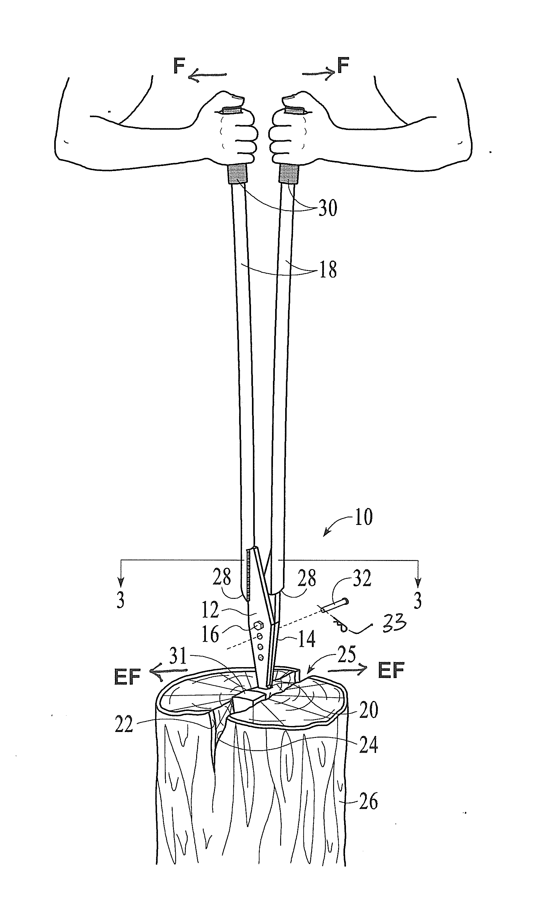
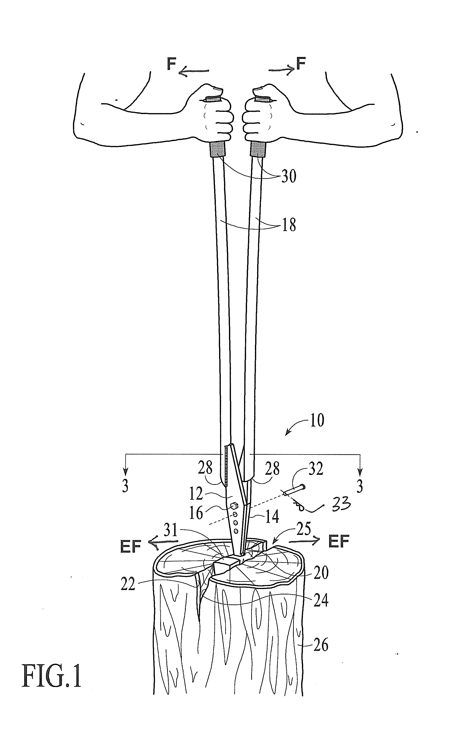
[0014]FIG. 1 is a perspective view of a manually operable log splitter 10 of the present invention in accordance with the invention, showing its manner of use.

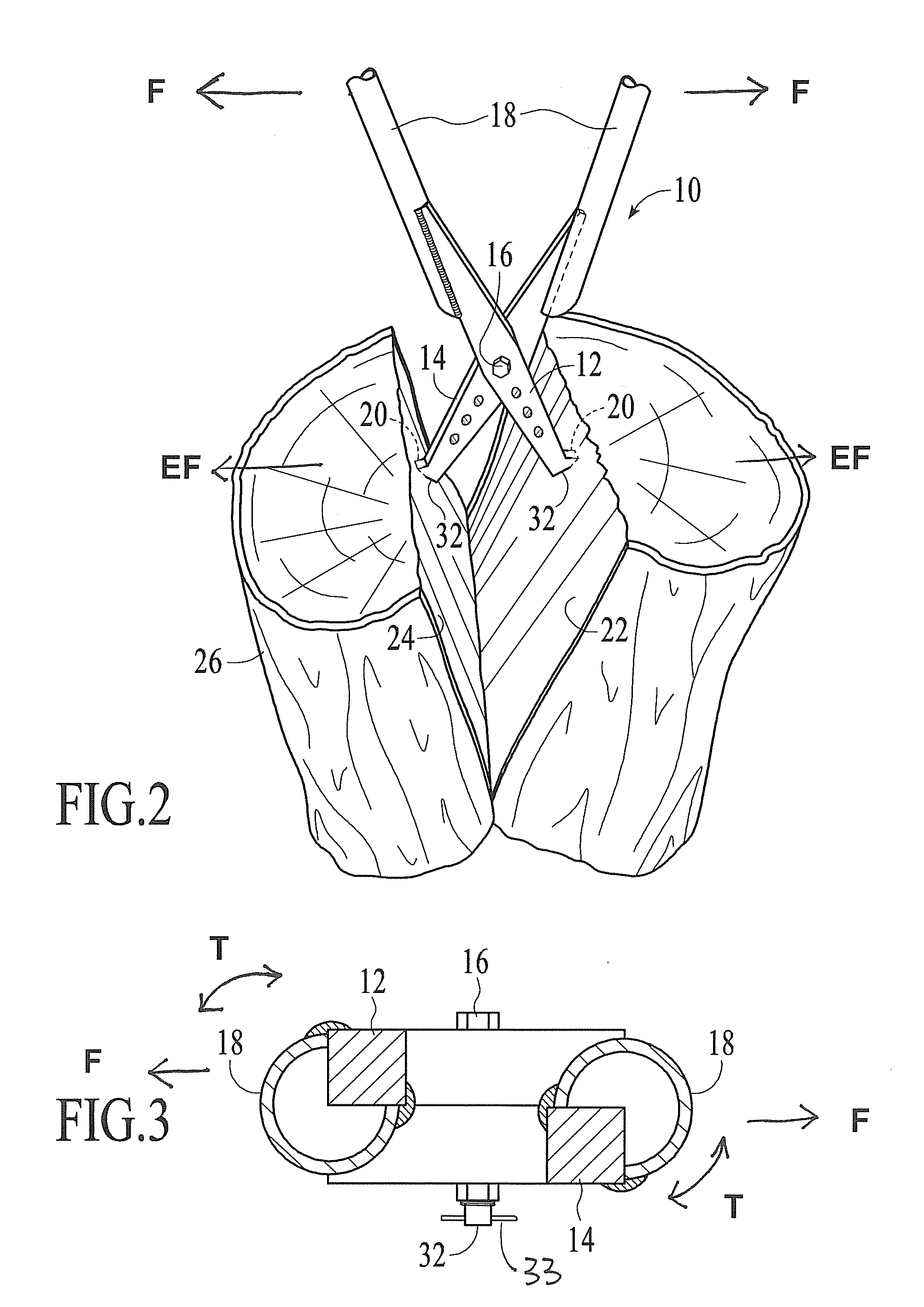
[0015]FIG. 2 is a similar perspective view, but of manually operable log splitter 10 of the present invention at the conclusion of its use to split a log.

[0016]FIG. 3 is a cross-section view, taken along the line 3-3′ of the manually operable log splitter 10 of the present invention in FIG. 1.

DETAILED DESCRIPTION OF THE PREFERRED EMBODIMENT

[0017]The description that follows is presented to enable one skilled in the art to make and use the present invention, and is provided in the context of a particular application and its requirements. Various modifications to the disclosed embodiments will be apparent to those skilled in the art, and the general principals discussed below may be applied to other embodime...


PUM


Abstract

A manually-operable log splitter for use with a splitting wedge has a pair of jaws pivotable about a point. Each jaw is connected to a handle extending away from its associated jaw from the pivot point. The jaws have a tip smaller than a width of the splitting wedge with which the splitter is used. The jaws and handles are dimensioned and configured for insertion beside the splitting wedge when embedded in a log. Manual application of force F on each handle outward from the pivot point spreads the jaws and provides sufficient force for splitting the log. This tool is particularly suited for small scale log splitting, such as by a home owner for personal use.

Description

RELATED APPLICATIONS[0001]This application is related to U.S. patent application Ser. No. 06 / 313,747 filed Oct. 22, 1981, entitled MANUALLY OPERABLE LOG SPLITTER, which is incorporated herein by reference in its entirety, and claims any and all benefits to which it is entitled therefrom.FIELD OF THE INVENTION[0002]This invention relates to a hand-operated tool for splitting logs. More particularly, it relates to such a tool which may be used to complete the splitting of a log rapidly and conveniently when a splitting wedge is embedded in the log.BACKGROUND OF THE INVENTION[0003]In the use of a splitting wedge and sledge hammer for splitting logs, a substantial percentage of the time the wedge will become embedded in the log without completing the splitting of the log into two pieces. Further, many logs require multiple blows to complete the splitting, even if the wedge does not become embedded in the log without completing the splitting. The use of crow-bars and similar tools to fre...

Claims


Application Information

Patent Timeline
Patent Type & Authority Applications(United States)
IPC IPC(8): B27L7/06
CPCB27L7/06B27L7/005
Inventor LARSON, MARCUS R.CROWELL, MICHAEL G.
Owner LARSON MARCUS R
Learn More