Pneumatic tire

a technology of pneumatic tires and tires, applied in the field of pneumatic tires, can solve the problems of achieve the effects of preventing heel and toe wear, reducing stiffness, and reducing stiffness

Inactive Publication Date: 2011-06-02
TOYO TIRE & RUBBER CO LTD
View PDF3 Cites 2 Cited by
  • Summary
  • Abstract
  • Description
  • Claims
  • Application Information

AI Technical Summary

Benefits of technology

[0013]When the above pneumatic tire is mounted on a vehicle, irrespective of the direction of the mounted tire, either of the first type sipes or the second type sipes has a step portion on the sipe wall surface located at the leading side. In such sipes, compared to sipe wall surface with the step portion located at the leading side, the sipe wall surface with no step portion located at the trailing side has a lower stiffness. In this pneumatic tire, the first type sipes and the second type sipes are formed in one-side closed sipes. In the side edge portion of the land portion, in the circumferential direction, the stiffness difference is increased in the land portion between the sipes. In this portion, the heel and toe wear is generated from the earlier stage of use of the tire. With this arrangement, irrespective of the direction of the mounted tire, in the side edge portion of the land portion, the wear sacrifice portion is formed in an earlier stage; thereby heel and toe wear can be prevented from expanding into the entire of the land portion. Also, by providing the above-described step portion, even when the volume of the first / second type sipes as the one-side closed sipes is reduced, a stiffness difference can be made large in the circumferential direction in the land portion between the sipes. As a result, as described above, while preventing the partial wear from being generated, clack generation due to the sipe can be prevented.
[0014]In the pneumatic tire, it is preferred that the tread surface is formed with a lateral groove crossing the main groove, each of the first type sipe closest to the lateral groove and the second type sipe closest to the lateral groove has the step portion on the sipe wall surface located at the lateral groove side. With this arrangement, in the sipe closest to the lateral groove, the stiffness of the sipe wall surface located at the lateral groove side is increased. Therefore, the stiffness of the land portion between the sipe and the lateral groove is increased. As a result, in this pneumatic tire, clacks can be prevented from being generated at end portion of the land portion.
[0015]In the pneumatic tire, it is preferred that each of the first type sipe and the second type sipe has a concave portion in the sipe wall surface located at the side where the step portion is not formed. With this arrangement, since the stiffness of the sipe wall surface with no step portion is further reduced, the stiffness difference is made larger in the land portion between the sipes in the circumferential direction. As a result, in this pneumatic tire, the heel and toe wear can be effectively prevented from expanding into the entire of the land portion.

Problems solved by technology

In this portion, the heel and toe wear is generated from the earlier stage of use of the tire.

Method used


Image

  • Pneumatic tire
  • Pneumatic tire
  • Pneumatic tire

Examples


example 1

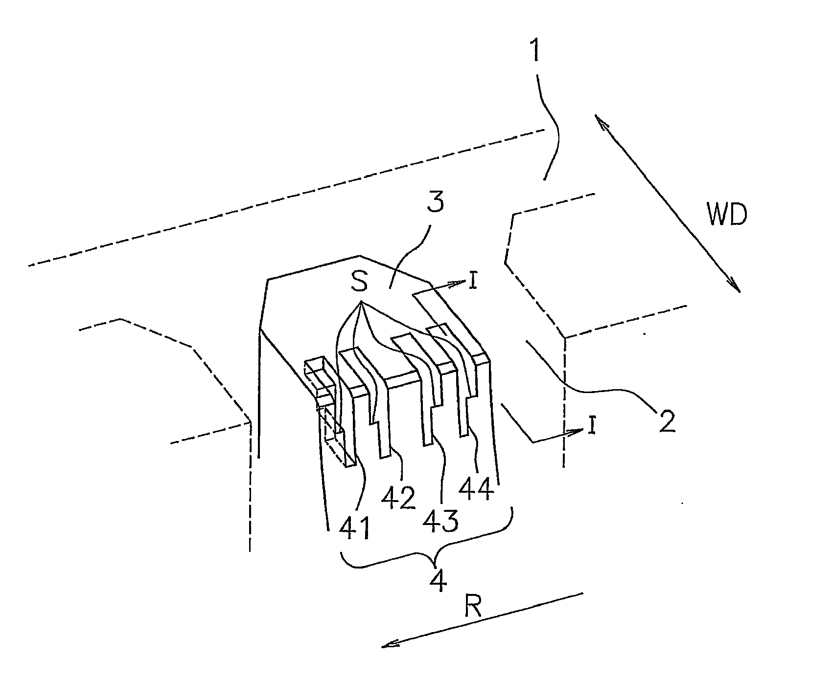
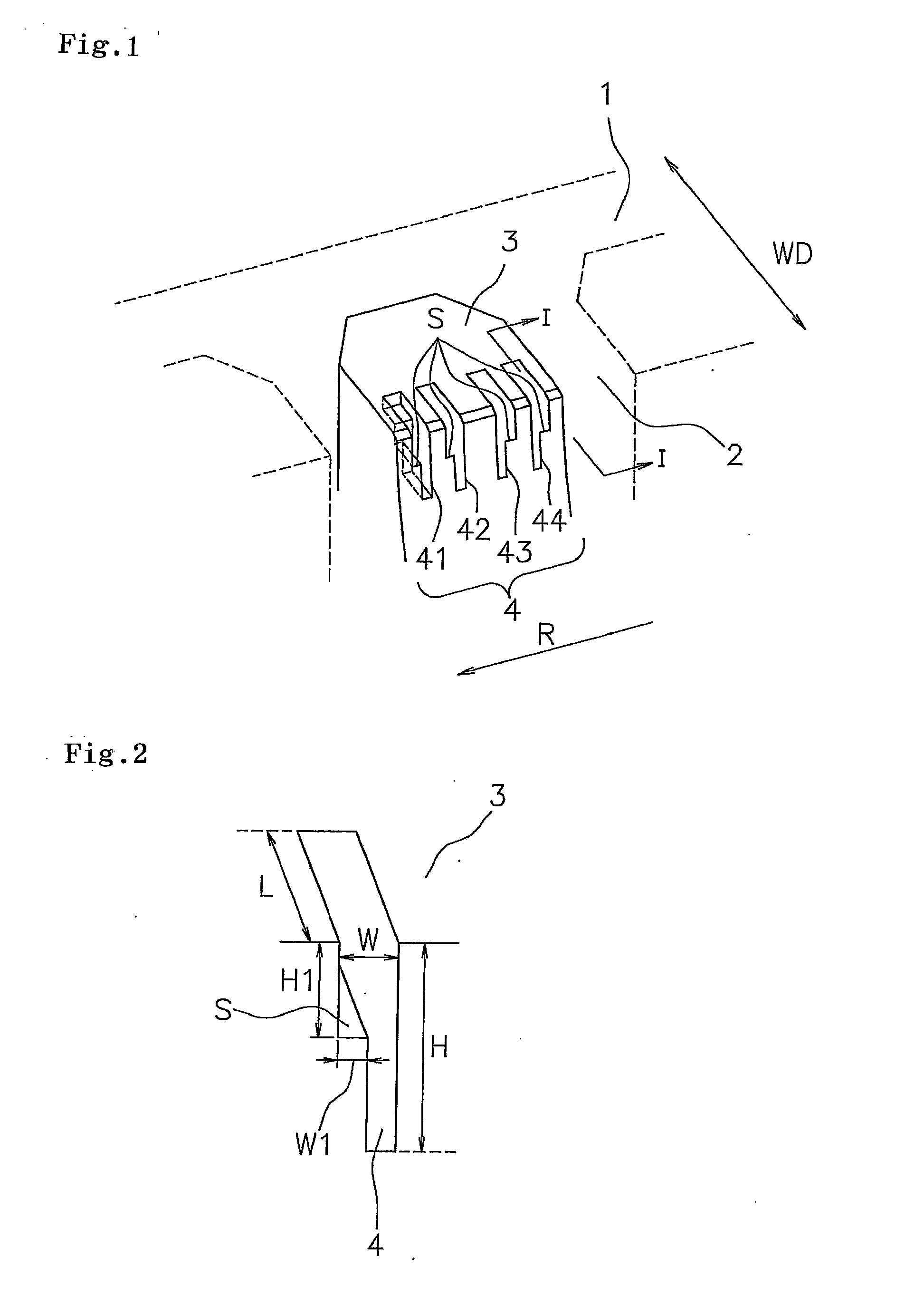
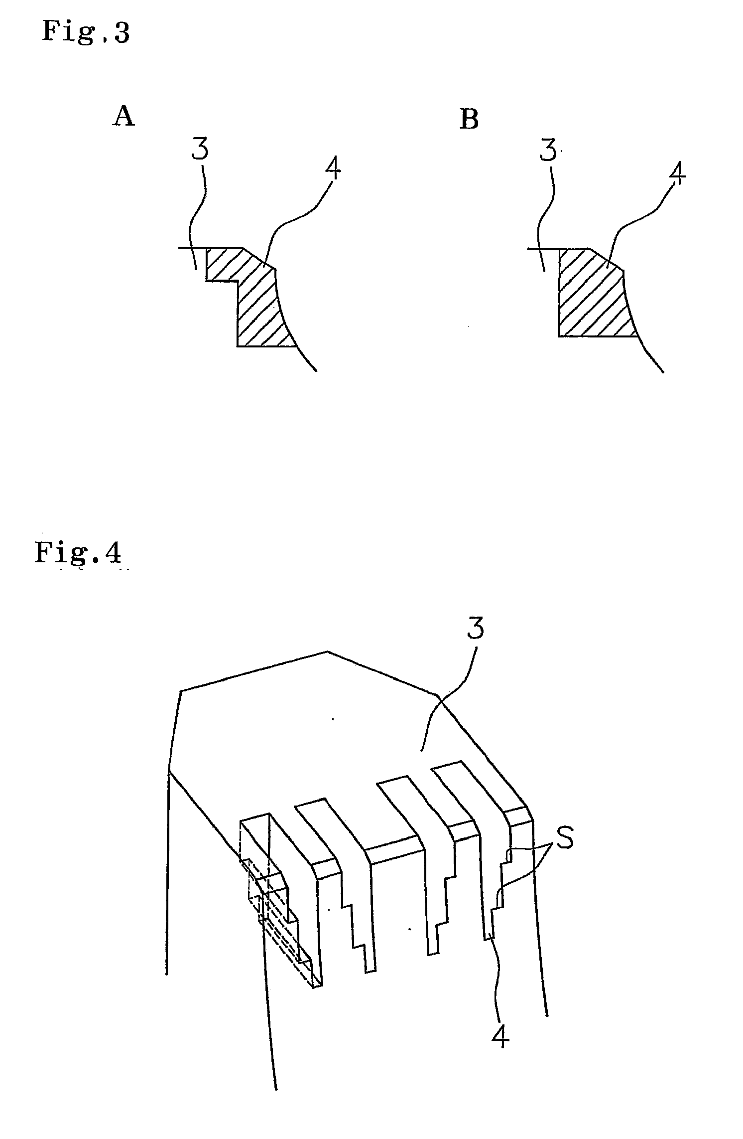
[0045]A pneumatic tire including a shoulder block shown in FIG. 1 was prepared (one-side closed sipes 4 shown in FIG. 2 End FIG. 3A were formed and the following settings were made: L=5 mm, H=20 mm, W=1 mm, H1=10 mm, W1=0.5 mm). Table 1 shows the result of the above evaluation made by using such a pneumatic tire.

example 2

[0046]A following pneumatic tire was prepared. That is, a pneumatic tire which had the same structure as that in Example 1 excepting a point that, in the pneumatic tire including shoulder block shown in FIG. 1, the direction of the Sipe wall surface with the step portion S was changed as shown in FIG. 7A. Table 1 shows the result of the above evaluation made by using such a pneumatic tire.

example 3

[0047]A following pneumatic tire was prepared. That is, a pneumatic tire which had the same structure as that in Example 1 excepting a point that, in the pneumatic tire including shoulder block shown in FIG. 1, one-side closed sipes 4 which had two step portions S as shown in FIG. 7B employed. Table 1 shows the result of the above evaluation made by using such a pneumatic tire.


PUM


Abstract

An object of the present invention is to provide a pneumatic tire which prevents not only partial wear but also clack generation in land portion of tread surface. In order to achieve the object, the land portion is formed with a first type sipe having a step portion extending in a width direction of the tire on one sipe wall surface and a second type sipe having a step portion extending in the width direction of the tire on a sipe wall surface facing in the opposite direction of the first type sipe as viewed in the circumferential direction of the tire.

Description

BACKGROUND OF THE INVENTION[0001]1. Field of the Invention[0002]The present invention relates to a pneumatic tire comprising a tread surface including a land portion defined by a main groove extending in a circumferential direction of the tire. The pneumatic tire of the present invention is particularly useful for a heavy duty pneumatic tire.[0003]2. Description of the Related Art[0004]In heavy duty pneumatic tires used for trucks and buses, repeated use may cause partial wear generated notably in shoulder portion on land portion. For example, in the case of tires having blocks formed as land portion in shoulder portion, partial wear tends to be generated in a side edge portion and a trailing side portion of the block (shadowed in FIG. 8). Therefore, in heavy duty pneumatic tires, there is a problem of a partial wear, so-called heel and toe wear or the like; that is, a wear difference is generated in the trailing side and the leading side of the block as viewed in a circumferential ...

Claims


Application Information

Patent Timeline
Patent Type & Authority Applications(United States)
IPC IPC(8): B60C11/13
CPCB60C11/1392B60C11/12B60C11/1376B60C2011/1227B60C11/1218
Inventor HITOTSUYANAGI, TOMOHIRO
Owner TOYO TIRE & RUBBER CO LTD
Why Eureka
Try Eureka