Roller Mill With Gas Duct

a technology of gas ducts and roller mills, applied in the field of roller mills, can solve problems such as low pressure loss

Active Publication Date: 2011-06-02
F L SMIDTH & CO AS
View PDF7 Cites 6 Cited by
  • Summary
  • Abstract
  • Description
  • Claims
  • Application Information

AI Technical Summary

Benefits of technology

[0004]It is the objective of the present invention to provide a roller mill by means of which the described disadvantages are significantly reduced.
[0006]This will ensure a significant reduction of the pressure loss in a roller mill and thus a significant reduction of the energy consumption of a roller mill. One or more gases may be introduced via a gas inlet connected to the annular duct. In this way the one or more gases introduced via the gas inlet to the annular duct are directed to the grinding table through the openings in the annular duct. The reduction of the pressure loss is achieved as the gas velocity through the openings of the annular duct just has to be sufficient to prevent the particles to flow radially into the openings of the annular duct and sufficient to ensure that the ground material is suspended in the gases. Hence the gas velocity can be kept low resulting in a low pressure loss.
[0009]In a further embodiment a mechanism, apparatus or device for introducing gases into the mill housing comprises a nozzle ring, through which one or more gases are directed, surrounding the grinding table and placed between the annular duct and the grinding table. In this way it is possible to introduce gases around the grinding table both vertically through the nozzle ring and horizontally through the annular duct whereby an advantageous gas flow in the mill housing can be achieved, making it possible to affect the particle size distribution curve.
[0010]In a further embodiment a mechanism, apparatus or device for introducing gases into the mill housing comprises two or more separate feed systems each comprising means such as a fan for introducing gases into the mill housing. The gases can either be blown or sucked through the feed systems. One feed system could introduce gases in a substantially vertical direction through a nozzle ring surrounding the grinding table and a second feed system could introduce gases substantially radially in the direction of and onto the grinding table through the openings in the annular duct. It is preferred that less than 50% of the gases are introduced through the nozzle ring and that the rest of the gases are introduced through the openings of the annular duct, but other distributions of the flow are also possible as long as the objective of lowering the fan energy consumption is achieved. Thus the major quantity of the introduced gases to the mill housing, coming from the openings of the annular duct, could be introduced at a low velocity resulting in a low pressure drop. Furthermore it is possible to introduce cold gases, i.e. the atmospheric air surrounding the roller mill, through one system and hot gases through the second system. The volume of cold gases is smaller than the volume of hot gases which means that the load on the fan subjected to cold gases would be relatively smaller. Furthermore, it is advantageous when some of the gases being introduced into the mill housing are made up of cold gases such as atmospheric air or recirculation gas from the mill system since this would lessen the requirements imposed upon the materials and components of the feed system as compared to a feed system for introducing hot gases. The relationship between the quantity of hot gases and colder gases, respectively, must be optimized relative to the process in the mill in order to minimize the energy consumption for the grinding process and the air flow process.
[0011]In a special embodiment the annular duct comprises a number of separate duct sectors around its circumference, where each duct sector has a gas inlet. In this way it is possible to control the introduction of gases around the grinding table thereby increasing the options for optimizing the gas flow.

Problems solved by technology

Hence the gas velocity can be kept low resulting in a low pressure loss.

Method used


Image

  • Roller Mill With Gas Duct
  • Roller Mill With Gas Duct
  • Roller Mill With Gas Duct

Examples


Embodiment Construction

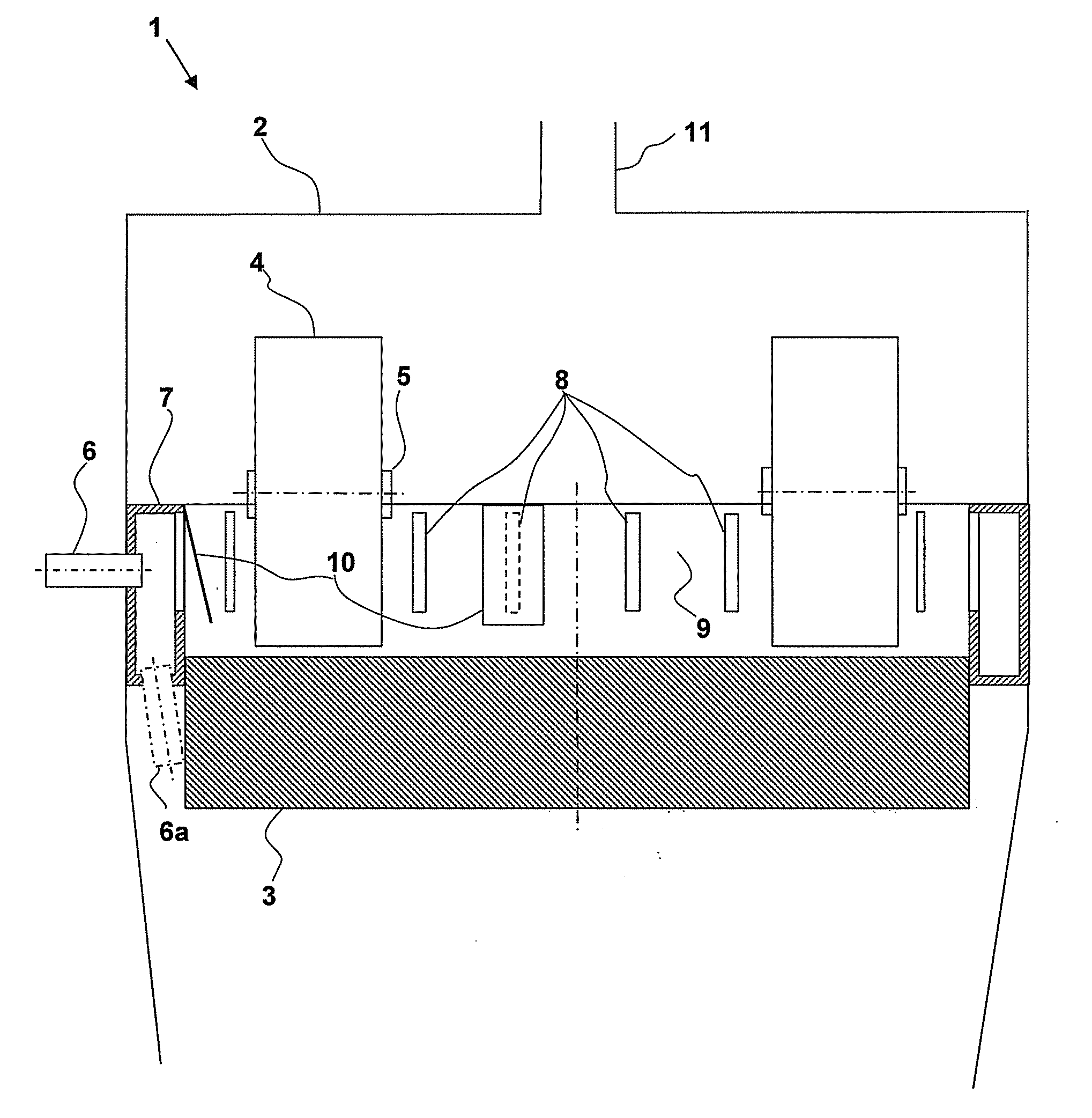
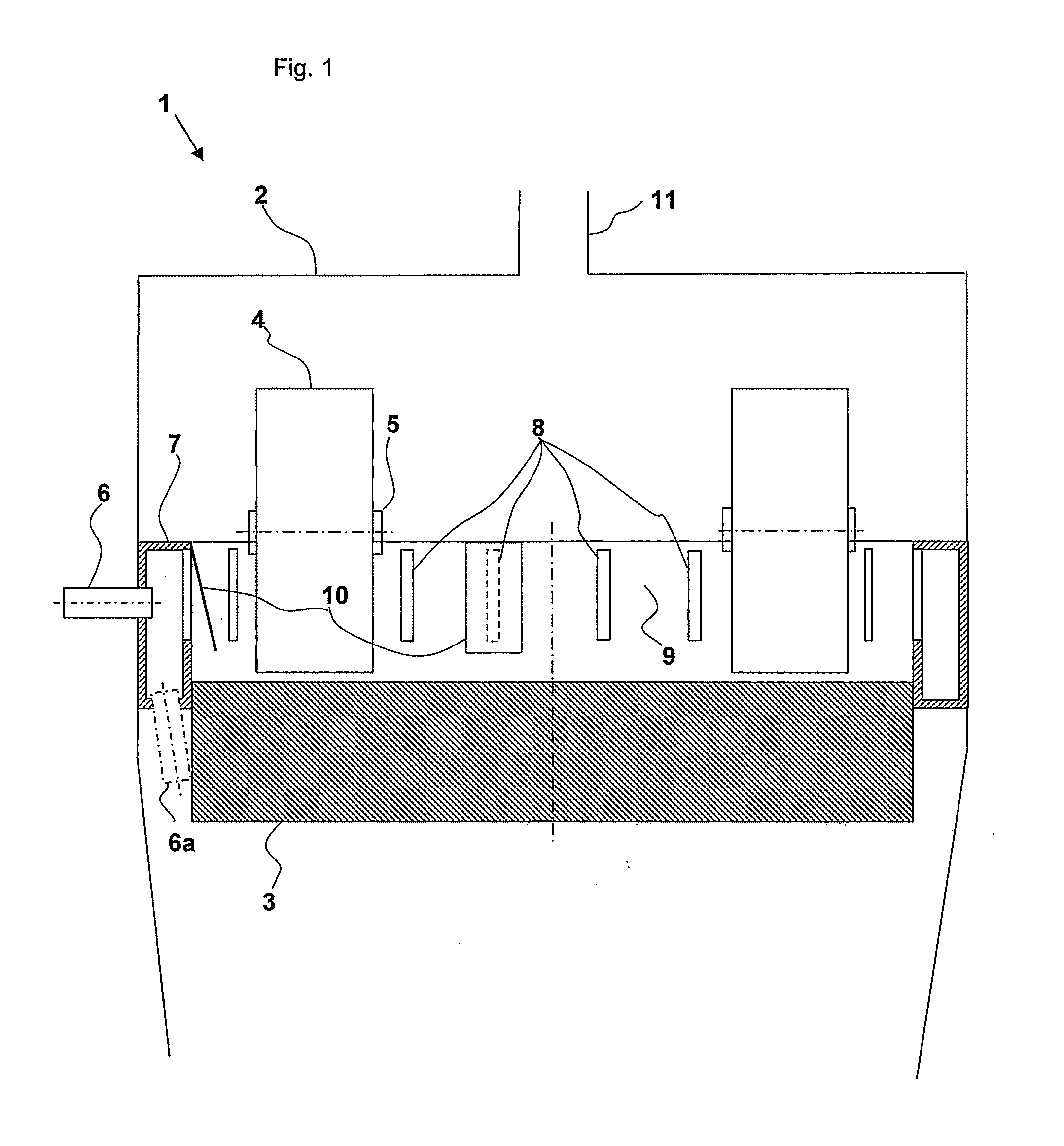
[0018]FIG. 1 shows a sectional view of a roller mill 1 with a mill housing 2 surrounding a substantially horizontal grinding table 3. A number of rollers 4, each rotating about a roller shaft 5, are configured for interactive operation with the grinding table 3. Raw material is continuously directed to the grinding table 3 through a feed inlet (not shown). Gases are introduced via a gas inlet 6 connected to an annular duct 7 which is situated around the outer circumference of the grinding table 3. The annular duct has openings 8 in a wall 9 facing the grinding table 3. In this way the gases introduced via the gas inlet 6 to the annular duct 7 are directed to the grinding table 3 through the openings 8 in the annular duct 7. The ground material suspended in gases is extracted through an outlet 11 in the upper part of the mill housing 2 by means of a fan (not shown). The openings 8 in the annular duct 7 are placed above the upper surface of the grinding table 3 and the annular duct 7 ...


PUM


Abstract

A roller mill for grinding particulate material such as cement raw materials, cement clinker and similar materials comprises a mill housing surrounding a substantially horizontal grinding table, a number of rollers each rotating about a roller shaft and configured for interactive operation with the grinding table and at least one mechanism or device for introducing gases into the mill housing. The at least one mechanism or device for introducing gases into the mill housing comprises an annular duct having openings in a wall facing the grinding table and being located around the outer circumference of the grinding table. As a consequence hereof, a significant reduction of the pressure loss in a roller mill and thus a significant reduction of energy consumption will be ensured.

Description

CROSS REFERENCE TO RELATED APPLICATIONS[0001]The present patent application is the United States national phase under 35 U.S.C. §371 of International Application No. PCT / EP2009 / 056695, filed on Jun. 1, 2009, and claiming priority to Danish Patent Application No. PA 2008 01049, filed on Jul. 30, 2008. The entirety of both of these applications are incorporated by reference herein.FIELD OF INVENTION[0002]The present invention relates to a roller mill for grinding particulate material such as cement raw materials, cement clinker and similar materials, said roller mill comprises a mill housing surrounding a substantially horizontal grinding table, a number of rollers, each rotating about a roller shaft, configured for interactive operation with the grinding table and means for introducing gases into the mill housing. The invention also relates to a method for carrying out the invention.BACKGROUND OF THE INVENTION[0003]A roller mill of the aforementioned kind is well-known from the paten...

Claims


Application Information

Patent Timeline
Patent Type & Authority Applications(United States)
IPC IPC(8): B02C15/00
CPCB02C15/14B02C15/001Y02P40/10
Inventor HORNING, BENT
Owner F L SMIDTH & CO AS
Why Eureka
Try Eureka