Trailing edge flap

a technology of railing edge and flap, which is applied in the direction of aircraft control, wing adjustment, aircraft components, etc., can solve the problems of performance loss at the higher deflection required for landing, and achieve the effect of improving the lifting potential of the arrangemen

Inactive Publication Date: 2011-06-02
AIRBUS OPERATIONS LTD
View PDF22 Cites 19 Cited by
  • Summary
  • Abstract
  • Description
  • Claims
  • Application Information

AI Technical Summary

Benefits of technology

The invention is advantageous in that when the flap elements move collectively they can be deployed sealed together like a standard single slotted flap to open up a single through slot between the fixed wing portion and the flap. This brings the benefits associated with standard single slotted flap arrangements. However, rotating at least the leading flap element about its axis makes i

Problems solved by technology

These are beneficial for take-off but suffer performance losses at the higher deflections required for landing.
Accordingly, it can be necessary for ai

Method used


Image

  • Trailing edge flap
  • Trailing edge flap
  • Trailing edge flap

Examples


Embodiment Construction

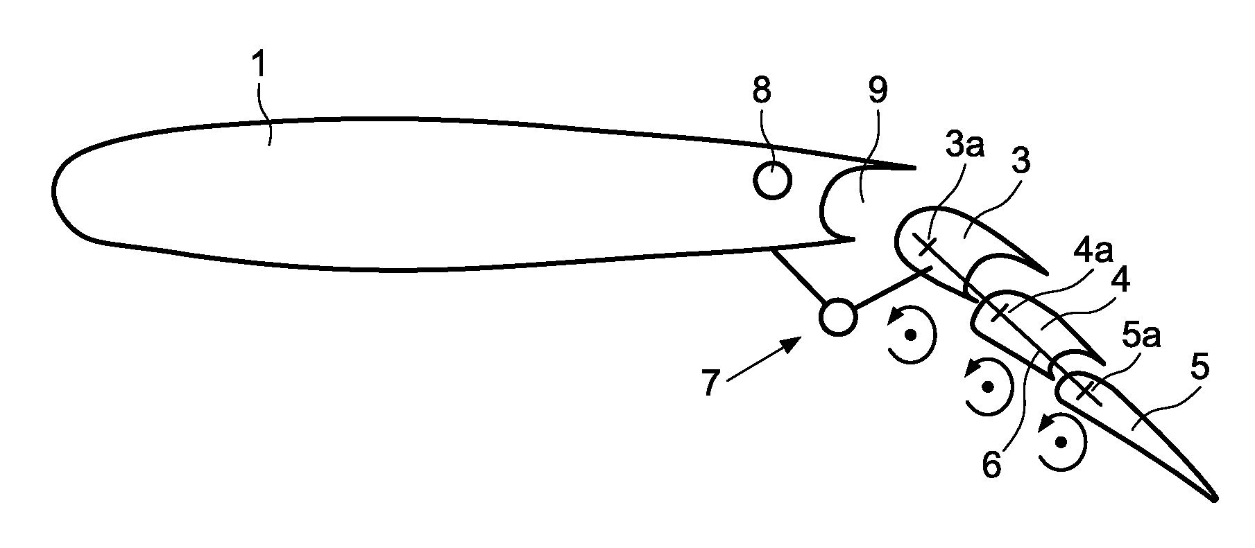
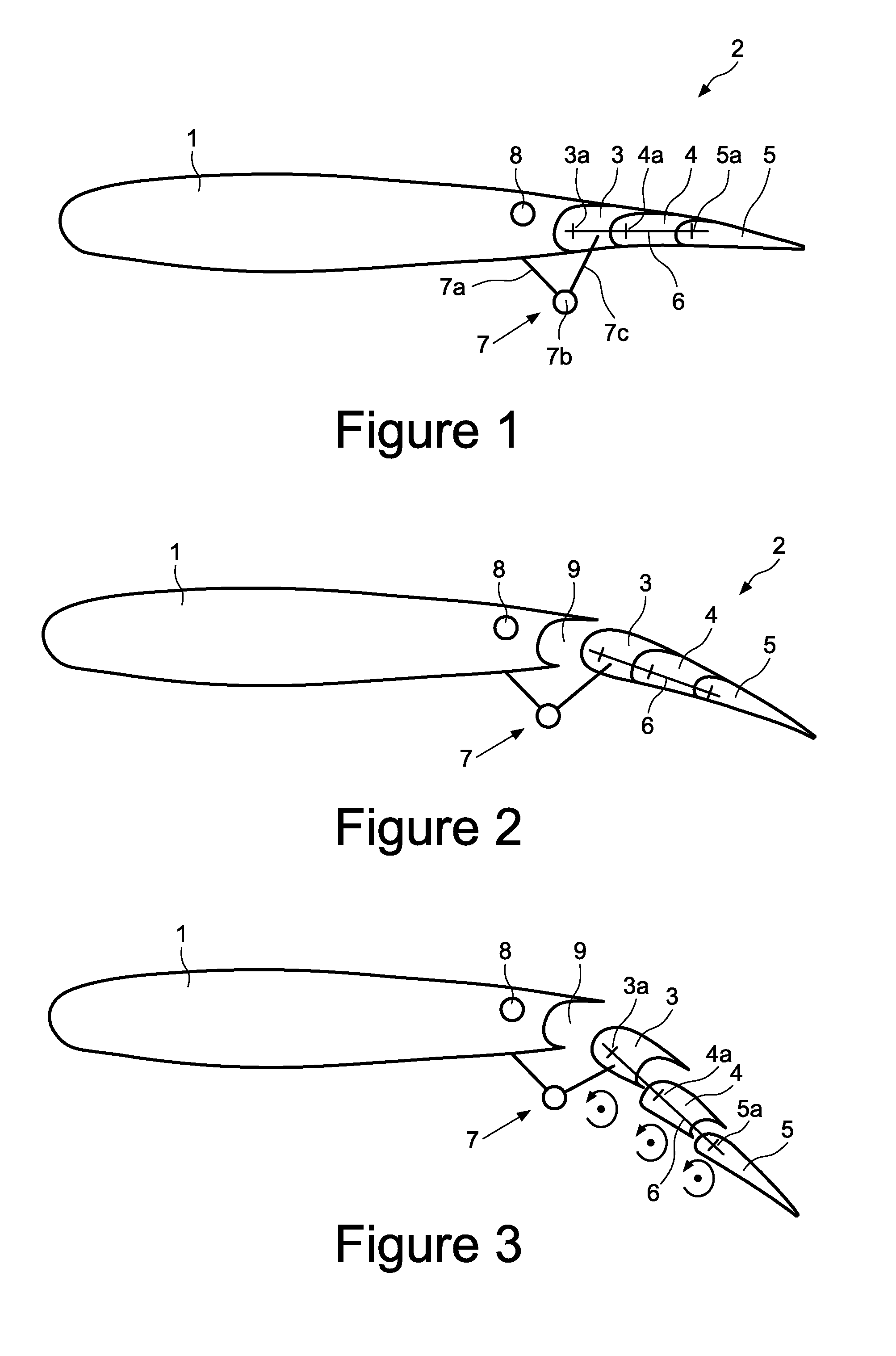
FIG. 1 shows an aircraft wing including a main fixed wing portion 1 and a trailing edge flap arrangement 2. The flap arrangement 2 includes an array of flap elements comprising a leading flap element 3, an intermediate flap element 4 and a trailing flap element 5.

The array of flap elements 3, 4, 5 are supported by a common strut 6 which in turn is pivotally supported from the fixed wing portion 1 by a drop hinge linkage arrangement 7. The drop hinge linkage arrangement includes a fixed strut 7a, a hinge point 7b and a drop link 7c. The fixed strut 7a is mounted to the fixed wing portion 1 and carries the hinge point 7b. The drop link 7c connects the common strut 6 to the hinge point 7b.

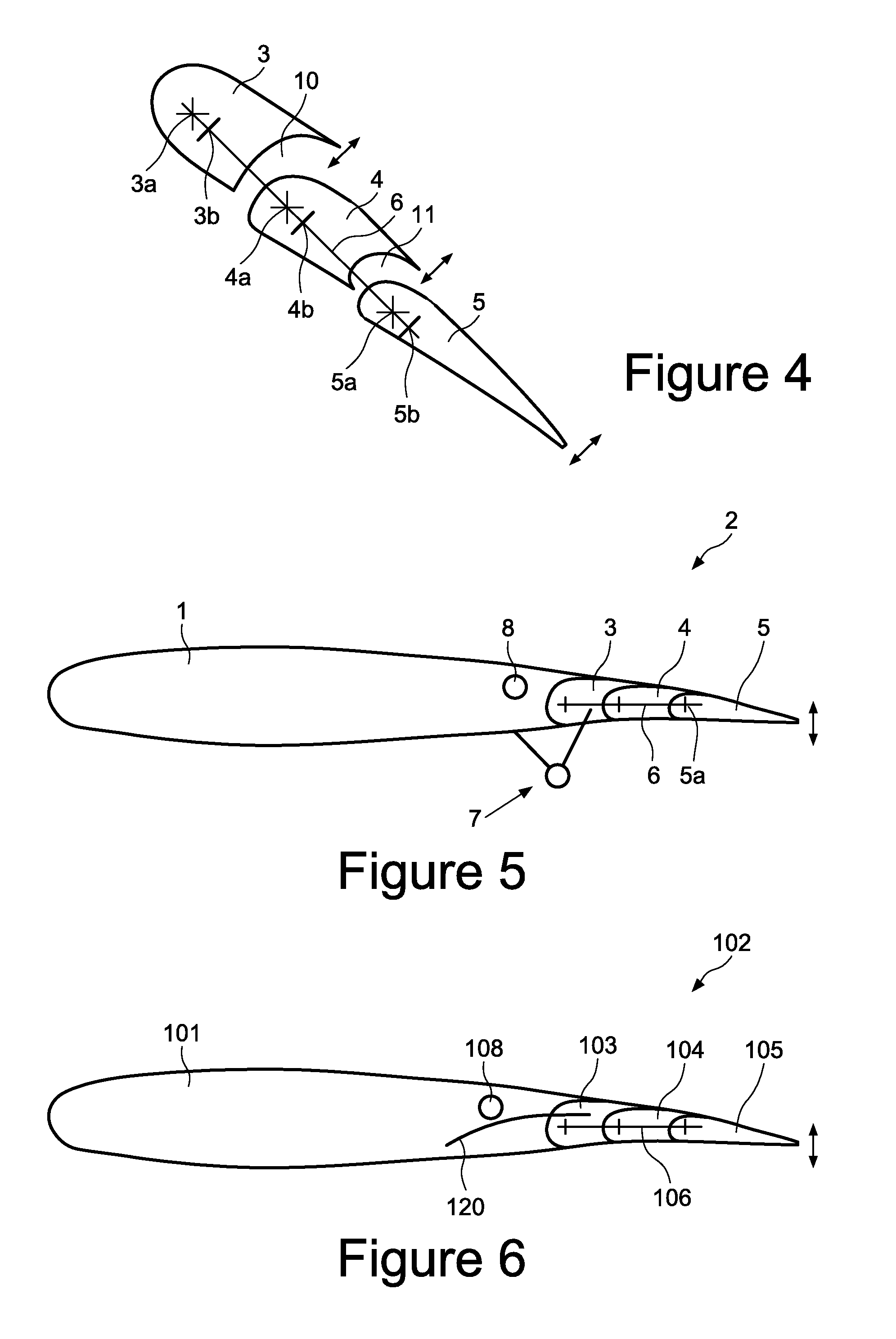
Each of the flap elements 3, 4, 5 is individually pivotally supported by the common strut 6 about a respective hinge point 3a, 4a, 5a. The hinge points 3a, 4a, 5a are disposed towards the leading edge of each of the flap elements 3, 4, 5 in the flap arrangement 2. The flap elements 3, 4, 5 are rotata...


PUM


Abstract

A trailing edge flap arrangement for an aircraft wing, comprising an array of flap elements moveable collectively between a retracted and an extended position, wherein at least the leading flap element is rotatable about its axis independently of the collective array movement. Also, a method of operating the trailing edge flap arrangement, comprising collectively moving the array of flap elements between a retracted and an extended position, and rotating at least the leading flap element about its axis independently of the collective array movement. The flap arrangement can be deployed as a single slotted flap which can be vented to further improve lift performance. The flap arrangement can also be operated to provide variable camber across the performance envelope.

Description

FIELD OF THE INVENTIONThe present invention relates to a trailing edge flap arrangement for an aircraft wing. The invention also relates to a method of operating a trailing edge flap arrangement.BACKGROUND OF THE INVENTIONAircraft wing trailing edge flaps are high lift devices which are typically deployed on take-off and landing to increase the lift coefficient by increasing the camber of the wing aerofoil. This can be achieved by rotating the flap downwardly about its hinge line with respect to the fixed wing portion. Some flaps, for example the Fowler flap, further increase the lift generated by the wing by also increasing the planform area of the wing. This is achieved by moving the flap along a track such that the flap moves aft and rotates downwardly when deployed. A “drop hinge flap” is a further type of flap having a hinge point typically below the fixed wing trailing edge, such that the flap moves aft and down with respect to the fixed wing as it rotates downwardly about its...

Claims


Application Information

Patent Timeline
IPC IPC(8): B64C3/50
CPCB64C9/26
Inventor MORRIS, STUART
Owner AIRBUS OPERATIONS LTD
Why Eureka
Try Eureka