System and method for driving light emitting devices using wireless communication module

a technology of wireless communication and light emitting devices, applied in the direction of electric lighting with batteries, lighting and heating apparatus, instruments, etc., can solve the problems of inability to power, user's inability to easily become aware of the presence, and increase implementation costs and time, so as to minimize the inconvenience of its construction and management

Inactive Publication Date: 2011-06-02
G-MODE
View PDF3 Cites 28 Cited by
  • Summary
  • Abstract
  • Description
  • Claims
  • Application Information

AI Technical Summary

Benefits of technology

[0007]Accordingly, the present invention has been made keeping in mind the above problems occurring in the prior art, and an object of the present invention is to provide a system and method for driving light emitting devices using a wireless communication module which is capable of minimizing inconveniences in its construction and management.
[0009]Still another object of the present invention is to provide a system and method for driving light emitting devices using a wireless communication module which is capable of preventing a dangerous situation from arising because of a failure using the self-diagnosis function of light emitting devices.

Problems solved by technology

This results in cost and time increases regarding implementation.
Accordingly, when a failure occurs in a part of the wired network, the light emitting devices cannot receive power, so that it is impossible to power them.
Accordingly, when the light emitting device fails, a user cannot easily become aware of the presence of a failure or the object responsible therefor.

Method used


Image

  • System and method for driving light emitting devices using wireless communication module
  • System and method for driving light emitting devices using wireless communication module
  • System and method for driving light emitting devices using wireless communication module

Examples


Embodiment Construction

[0028]Reference now should be made to the drawings, in which the same reference numerals are used throughout the different drawings to designate the same or similar components. Furthermore, if in the following description of the present invention, detailed descriptions of related well-known technologies may unnecessarily make the gist of the present invention unclear, and so detailed descriptions thereof will be omitted in the following description.

[0029]A system and method for driving light emitting devices according to an embodiment of the present invention will be described below in detail with reference to the accompanying drawings.

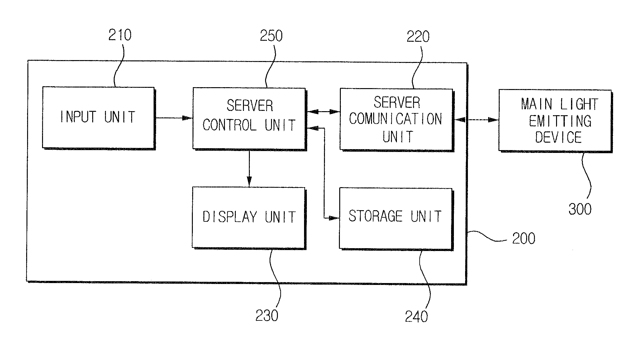
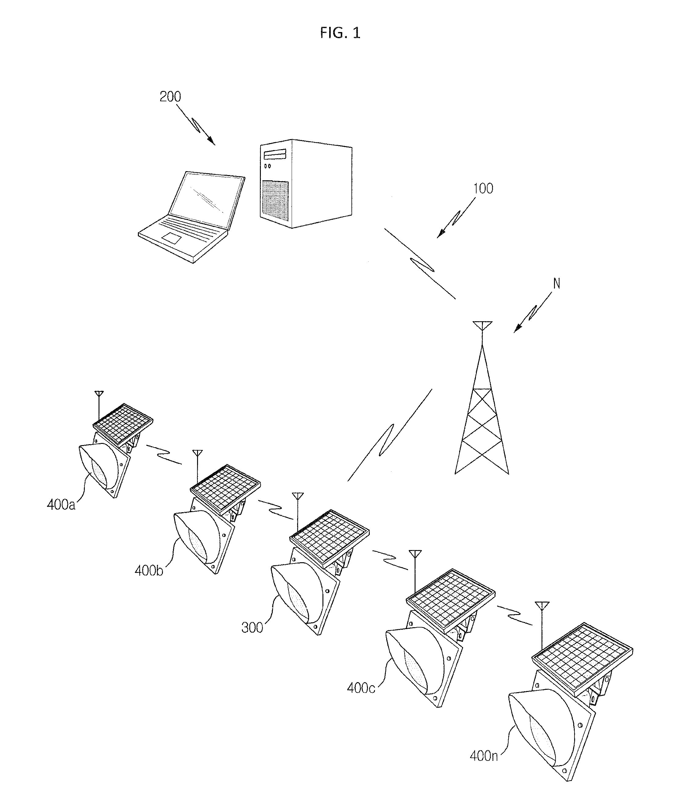
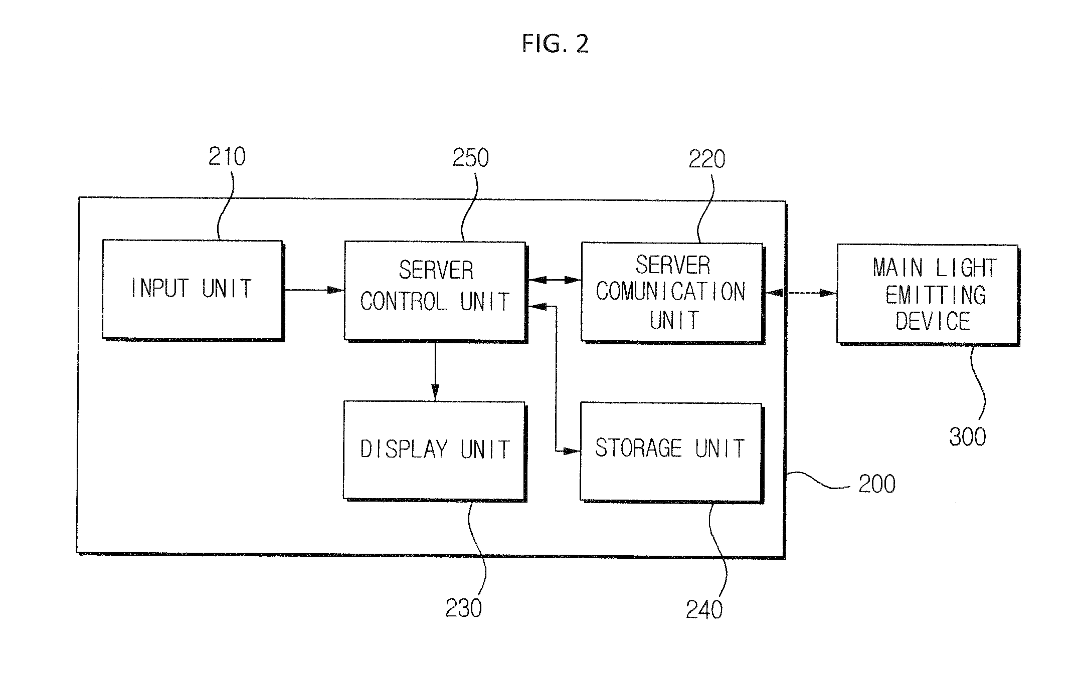
[0030]FIG. 1 is a diagram illustrating the configuration of a system for driving light emitting devices using a wireless communication module according to an embodiment of the present invention. As shown in FIG. 1, the system 100 for driving light emitting devices according to the embodiment of the present invention includes a central monitoring serve...


PUM


Abstract

Disclosed herein is a system for driving light emitting devices. The system for driving light emitting devices includes a main light emitting device and at least one sub-light emitting device. The main light emitting device includes a first communication unit for exchanging information with a central monitoring server and a close sub-light emitting device using a wireless communication module, a first light emitting unit having at least one light emitting element, and a first control unit for controlling the light emission of the first light emitting unit, and transmitting a command signal for controlling the sub-light emitting device to the sub-light emitting device. The sub-light emitting device includes a second communication unit for exchanging information with the main light emitting device, a second light emitting unit having at least one light emitting element, and a second control unit for controlling the light emission of the second light emitting unit.

Description

BACKGROUND OF THE INVENTION[0001]1. Field of the Invention[0002]The present invention relates generally to a system and method for driving light emitting devices using a wireless communication module, and, more particularly, to a system and method for driving light emitting devices using a wireless communication module which enable signals to be exchanged between a central processing server and light emitting devices located far away from each other using a commercial wireless communication network, and enable signals to be exchanged between the light emitting devices located within a local area using a local area wireless communication module.[0003]2. Description of the Related Art[0004]Light emitting devices such as fog guidance lamps are installed along roads or around facilities at predetermined intervals, and guide cars or walkers to locations. Conventional light emitting devices are connected to a central monitoring system by wiring, and are manually controlled by a manager. F...

Claims


Application Information

Patent Timeline
Patent Type & Authority Applications(United States)
IPC IPC(8): H01J1/60F21L4/00
CPCH05B37/0272H05B37/00H05B47/10H05B47/19H05B47/00H05B47/22
Inventor KIM, WON HAE
Owner G-MODE
Why Eureka
Try Eureka