System for the detection and the depiction of objects in the path of marine vessels

a technology for depicting and detecting objects, applied in the direction of distance measurement, instruments, and reradiation, can solve the problems of high risk of accidents, increased consequences of collision with floating objects, and increased number of containers flushed overboard, so as to improve the depiction

Active Publication Date: 2011-06-02
KONGSBERG MARITIME
View PDF6 Cites 31 Cited by
  • Summary
  • Abstract
  • Description
  • Claims
  • Application Information

AI Technical Summary

Benefits of technology

The patent describes a system that can see objects on and above the sea level, both during the day and night. It uses a laser to create a three-dimensional image, including accurate measurements of distance. The system is safe for use with binoculars and can detect the height of objects relative to the sea level. It works by sweeping a laser beam across the field of view and detecting the energy reflected from the surface. This makes it easier to see objects and wave height, which can be useful for marine applications.

Problems solved by technology

The patent text discusses the problem of collisions with floating objects in high-speed transportation, especially in sea travel. While there are some existing solutions for detection, such as radar and photosensitive cameras, they have limitations in accurately determining the distance of objects. The technical problem is to develop a system that can accurately detect the exact distance of objects within the view port, to improve safety and prevent accidents.

Method used


Image

  • System for the detection and the depiction of objects in the path of marine vessels
  • System for the detection and the depiction of objects in the path of marine vessels
  • System for the detection and the depiction of objects in the path of marine vessels

Examples


Embodiment Construction

[0021]The invention will now be detailed with reference to the attached drawings, wherein

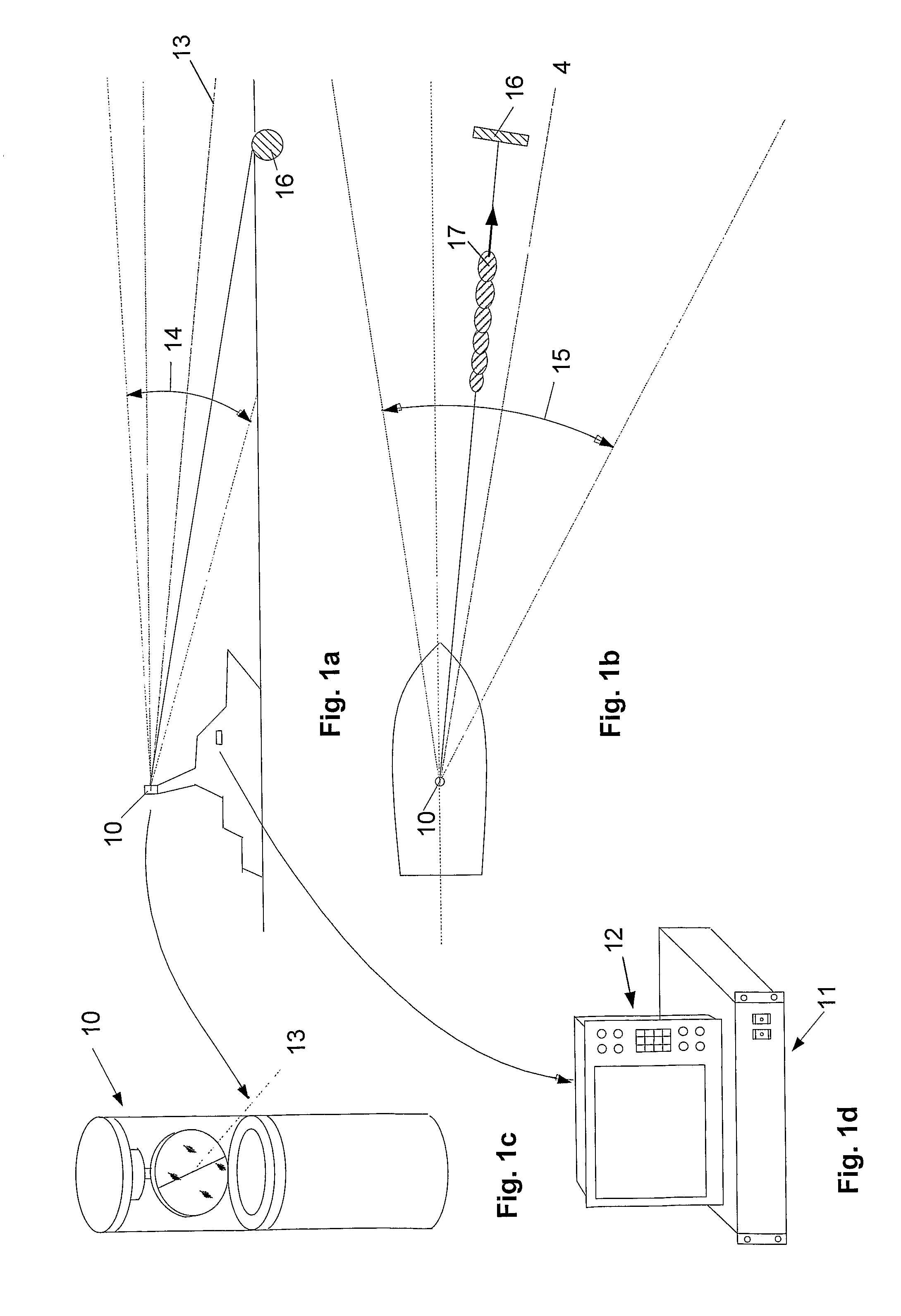
[0022]FIG. 1a and FIG. 1b show a vessel provided with a system in accordance with the invention,

[0023]FIG. 1c shows a sweeping unit,

[0024]FIG. 1d shows an operator panel / screen,

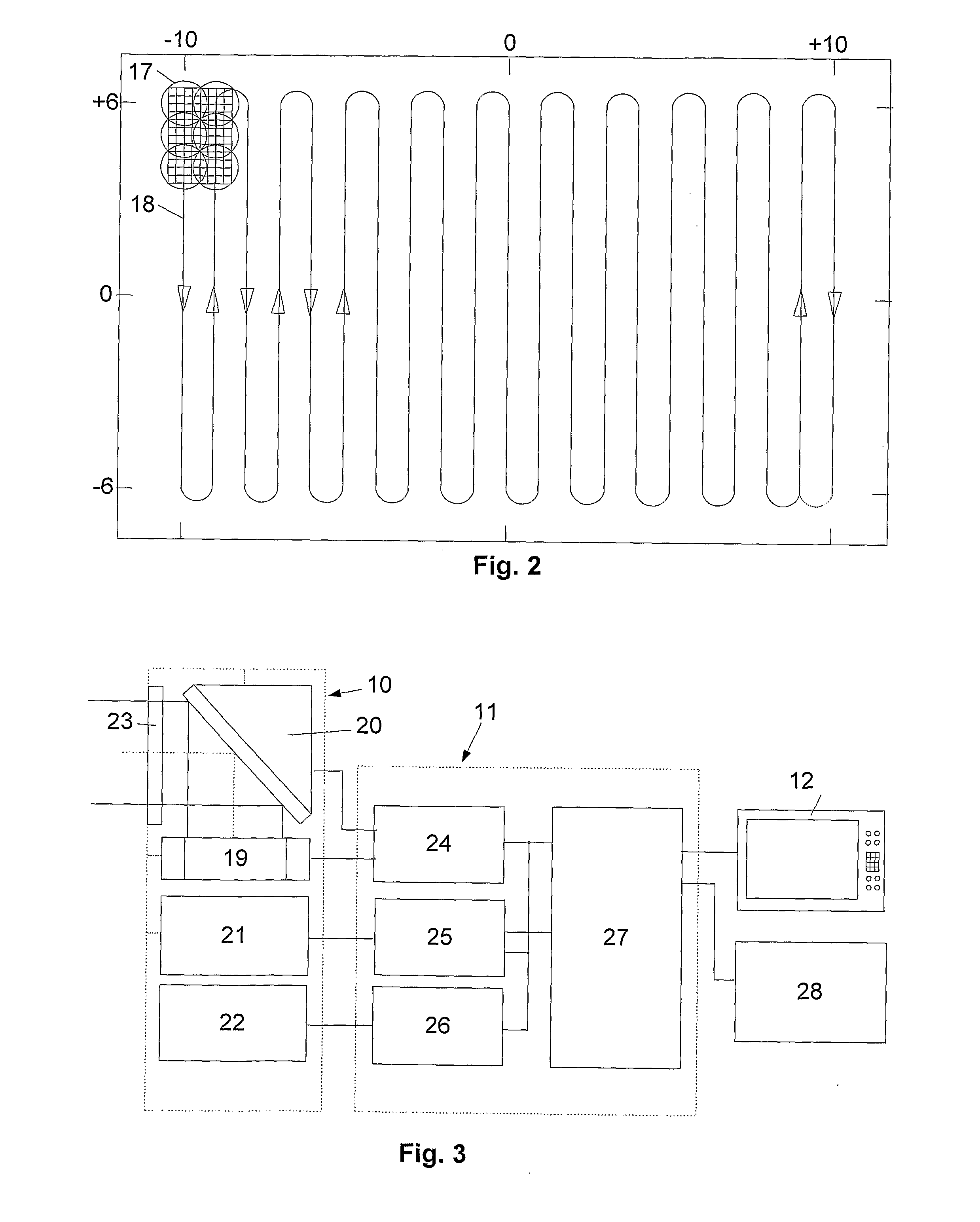
[0025]FIG. 2 shows an example of distribution of footprint and resolution elements in a plane perpendicular to the centre axis,

[0026]FIG. 3 shows a block diagram of a vessel installation,

[0027]FIG. 4 shows a cross section of a sweeping unit in accordance with the invention,

[0028]FIGS. 5a-d show the principle of a sweeping mechanism in accordance with the invention,

[0029]FIG. 6 shows schematically the analogue signal processing for the system, and

[0030]FIG. 7 shows schematically an overview of partial processes of the system.

[0031]Firstly referring to FIGS. 1a and 1B, which illustrate a vessel provided with a system in accordance with the invention, hereinafter referred to as a marine laser-radar-system, abbreviated MLR sy...


PUM


Abstract

System for detection and depiction of objects in the path of marine vessels and for warning about objects that may constitute a risk to the navigational safety. The system includes a sweeping unit for illumination of objects within the field of view of the system, including a light source which emits a beam within the field of view of the system, an optical sensor and pulse processing unit including optical detectors for monitoring of the beam output power and generation of a start pulse for measurement of distance, for detection/reception of radiant energy reflected from objects, including measurement of distance to the reflecting object(s) based on the time delay between emitted and reflected light, including energy and peak effect of the pulses. The sweeping unit sweeps the beam and the optical detector's instantaneous field of view over the sweep area, by means of first and second sweeping mechanisms, to obtain directional information related to the instantaneous radiation direction relative to the vessel.

Description


Claims


Application Information

Patent Timeline
Owner KONGSBERG MARITIME
Why Eureka
Try Eureka