IMAGE SIGNAL PROCESSING APPARATUS, IMAGE SIGNAL PROCESSING METHOD, IMAGE DISPLAY APPARATUS, TELEVISION RECEIVER, AND ELECTRONIC DEVICE (amended

Active Publication Date: 2011-06-02
SHARP KK
View PDF32 Cites 10 Cited by
  • Summary
  • Abstract
  • Description
  • Claims
  • Application Information

AI Technical Summary

Benefits of technology

[0049]As described above, an image signal processing apparatus of the present invention is an image signal processing apparatus provided in an image display apparatus for displaying an image, in accordance with image signals supplied to respective pixels, for every frame period corresponding to image signals for one (1) screen, the image signal processing apparatus including: a movement level detector section which detects a first movement level of a video image corresponding to a current frame period, by comparing (i) image signals corresponding to the current frame period with (ii) image signals corresponding to a previous frame period followed by the current frame period; a dividing section which divides one (1) frame period into a plurality of periods containing at least one sub-frame A period and at least one s

Problems solved by technology

An image display apparatus based on a hold-type display apparatus such as a liquid crystal display apparatus heretofore has had a problem in that quality of a moving image deteriorates (i.e., edge blur occurs).
This causes deterioration of quality of a moving image of the hold-type image display apparatus.
This causes a flicker.
This causes another problem of a decrease in luminance level.
This also contributes to deterioration of quality of a moving image.
However, the method has a difficulty in completely accurate estimation o

Method used


Image

  • IMAGE SIGNAL PROCESSING APPARATUS, IMAGE SIGNAL PROCESSING METHOD, IMAGE DISPLAY APPARATUS, TELEVISION RECEIVER, AND ELECTRONIC DEVICE (amended
  • IMAGE SIGNAL PROCESSING APPARATUS, IMAGE SIGNAL PROCESSING METHOD, IMAGE DISPLAY APPARATUS, TELEVISION RECEIVER, AND ELECTRONIC DEVICE (amended
  • IMAGE SIGNAL PROCESSING APPARATUS, IMAGE SIGNAL PROCESSING METHOD, IMAGE DISPLAY APPARATUS, TELEVISION RECEIVER, AND ELECTRONIC DEVICE (amended

Examples


Example

[0068]The following describes one embodiment of the present invention.

Embodiment

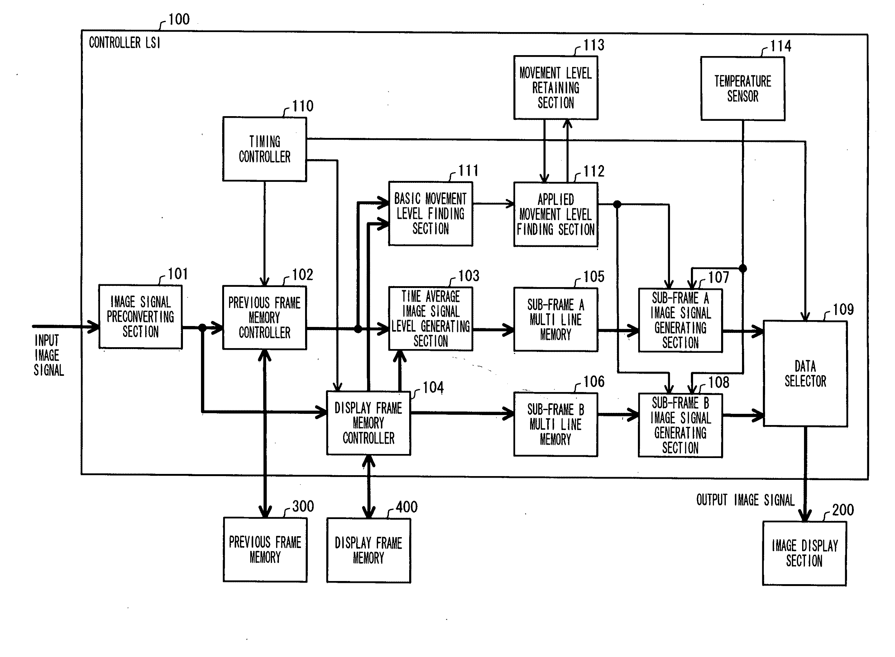
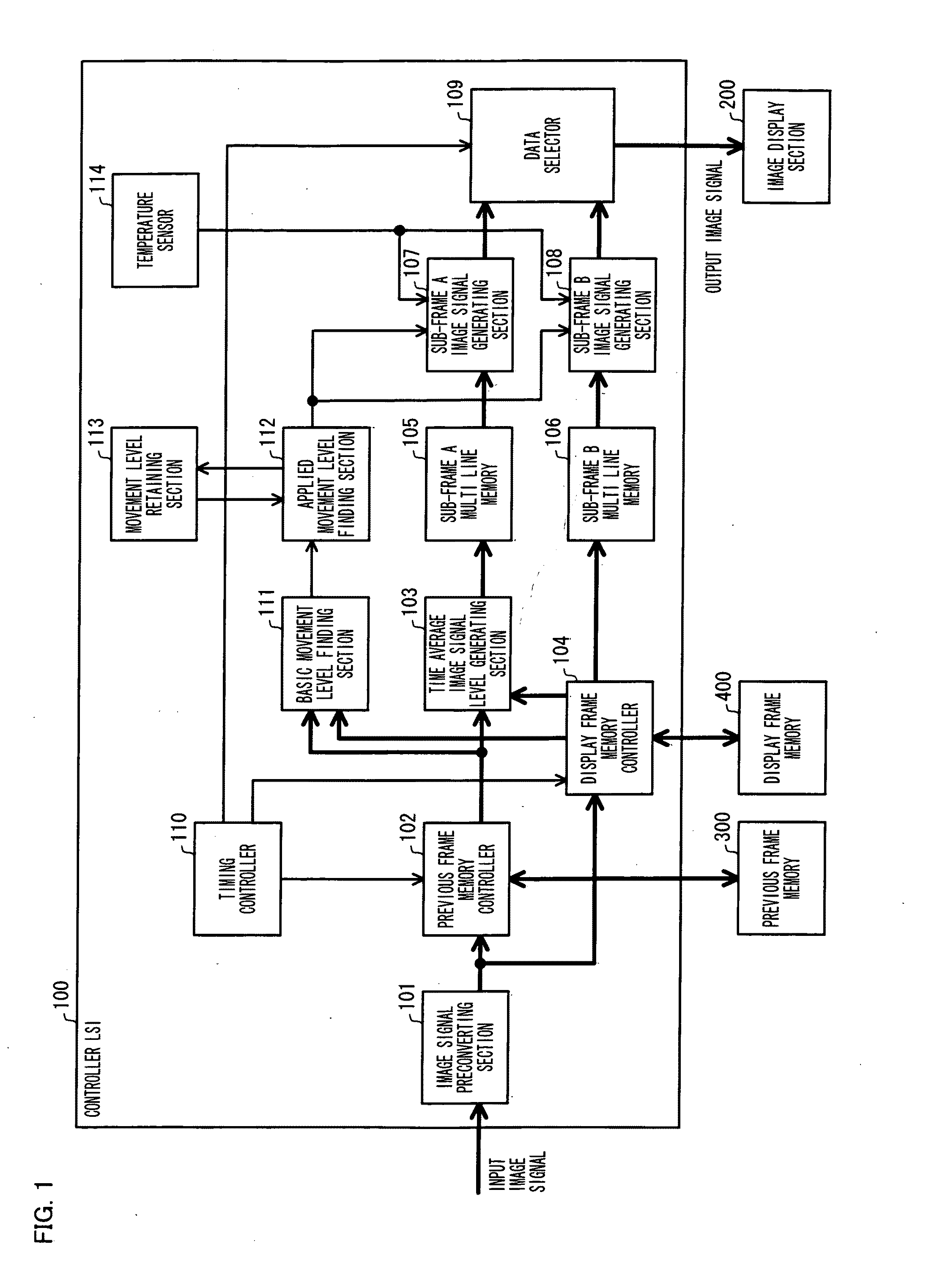
[0069]The present embodiment premises an image signal processing apparatus provided in an image display apparatus in which a hold-type display apparatus such as a liquid crystal display apparatus is used and which displays an image, in accordance with image signals supplied to respective pixels, for every frame period corresponding to image signals for one screen. On this premise, the present embodiment is characterized in that the following processes are carried out by the image signal processing apparatus.

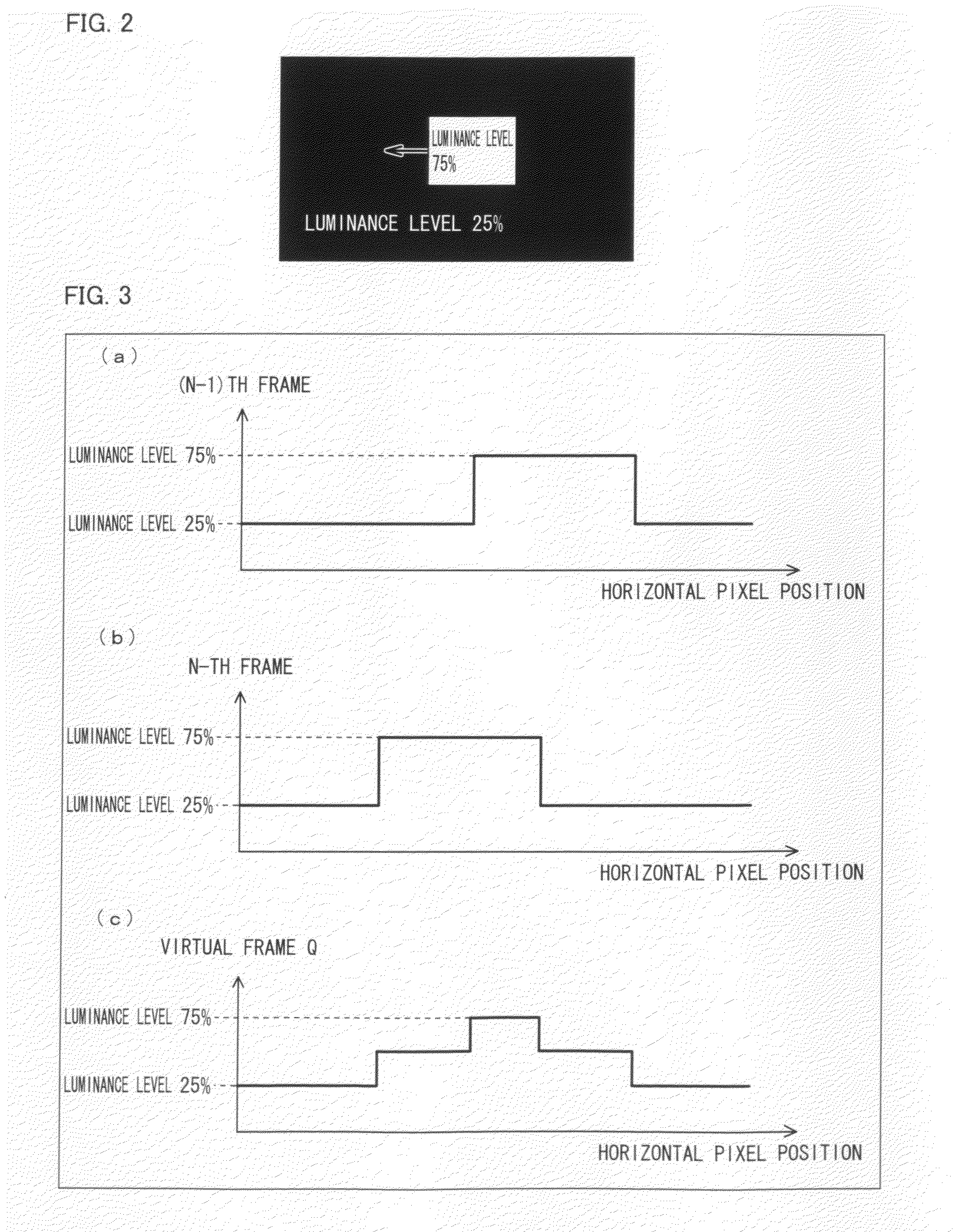
[0070]That is, in displaying an N-th frame, the image signal processing apparatus of the present embodiment generates a virtual sub-frame Q from image signals of an (N−1)th frame and an N-th frame, i.e., two adjacent frames so that each of pixels of the virtual sub-frame Q has, as its image signal level, an average of an image signal level of a corresponding pixel of the (N−1)th frame and that of the ...


PUM


Abstract

An image signal processing apparatus includes: a basic movement level finding section for detecting a movement level of a video image; a timing controller for dividing one frame period into a plurality of periods containing a sub-frame A period and a sub-frame B period; a sub-frame A image signal generating section for subjecting, to a smoothing process, image signals which are supplied to pixels, in the sub-frame A period, in accordance with the movement level of the video image; a sub-frame B image signal generating section for subjecting, to an emphasizing process, image signals which are supplied to pixels, in the sub-frame B period, in accordance with the movement level of the video image; and an applied movement level finding section for finding, from a movement level of a video image of a current frame period and a movement level of a video image of a previous frame period, an applied movement level which is applied to the sub-frame A image signal generating section and/or the sub-frame B image signal generating section.

Description

TECHNICAL FIELD[0001]The present invention relates to an image signal processing apparatus which improves quality of a moving image of an image display apparatus based on a hold-type display apparatus such as a liquid crystal display apparatus.BACKGROUND ART[0002]An image display apparatus based on a hold-type display apparatus such as a liquid crystal display apparatus heretofore has had a problem in that quality of a moving image deteriorates (i.e., edge blur occurs).[0003]The following explains deterioration of quality of a moving image (edge blur) of a conventional hold-type display apparatus, by taking, as an example, a case where as illustrated in FIG. 2, a region indicated by image signals having a luminance level of 75% horizontally moves on a background indicated by image signals having a luminance level of 25%.[0004]FIG. 13 shows a distribution of luminance levels of input image signals which are supplied to pixels on one horizontal line within one screen image indicated b...

Claims


Application Information

Patent Timeline
IPC IPC(8): H04N5/14
CPCG09G3/20H04N5/85G09G3/3611G09G2320/0247G09G2320/0261G09G2320/0271G09G2320/041G09G2320/103G09G2320/106G09G2340/0435G09G2340/16G09G2360/16G09G2360/18H04N5/142H04N5/144H04N5/66H04N5/782G09G3/2022
Inventor ISHIHARA, TOMOYUKI
Owner SHARP KK
Why Eureka
Try Eureka