

Instrumented prosthetic foot
a technology of instruments and prosthetic feet, applied in the field of prosthetic feet, can solve the problems of lack of predictive control strategies, and inability to achieve automatic control of complex mechanical systems
- Summary
- Abstract
- Description
- Claims
- Application Information
AI Technical Summary
Problems solved by technology
Method used
Image

Examples
Embodiment Construction
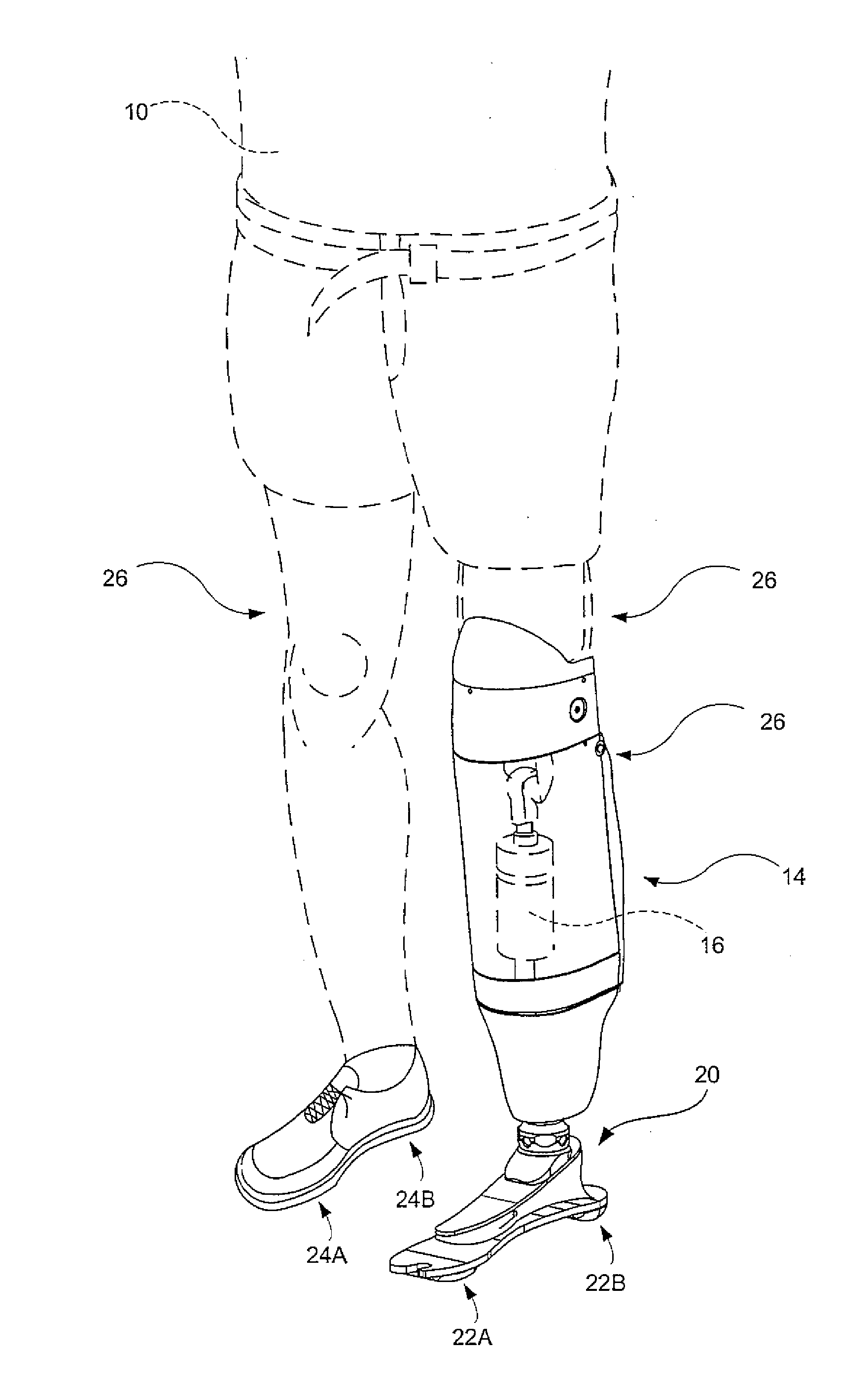
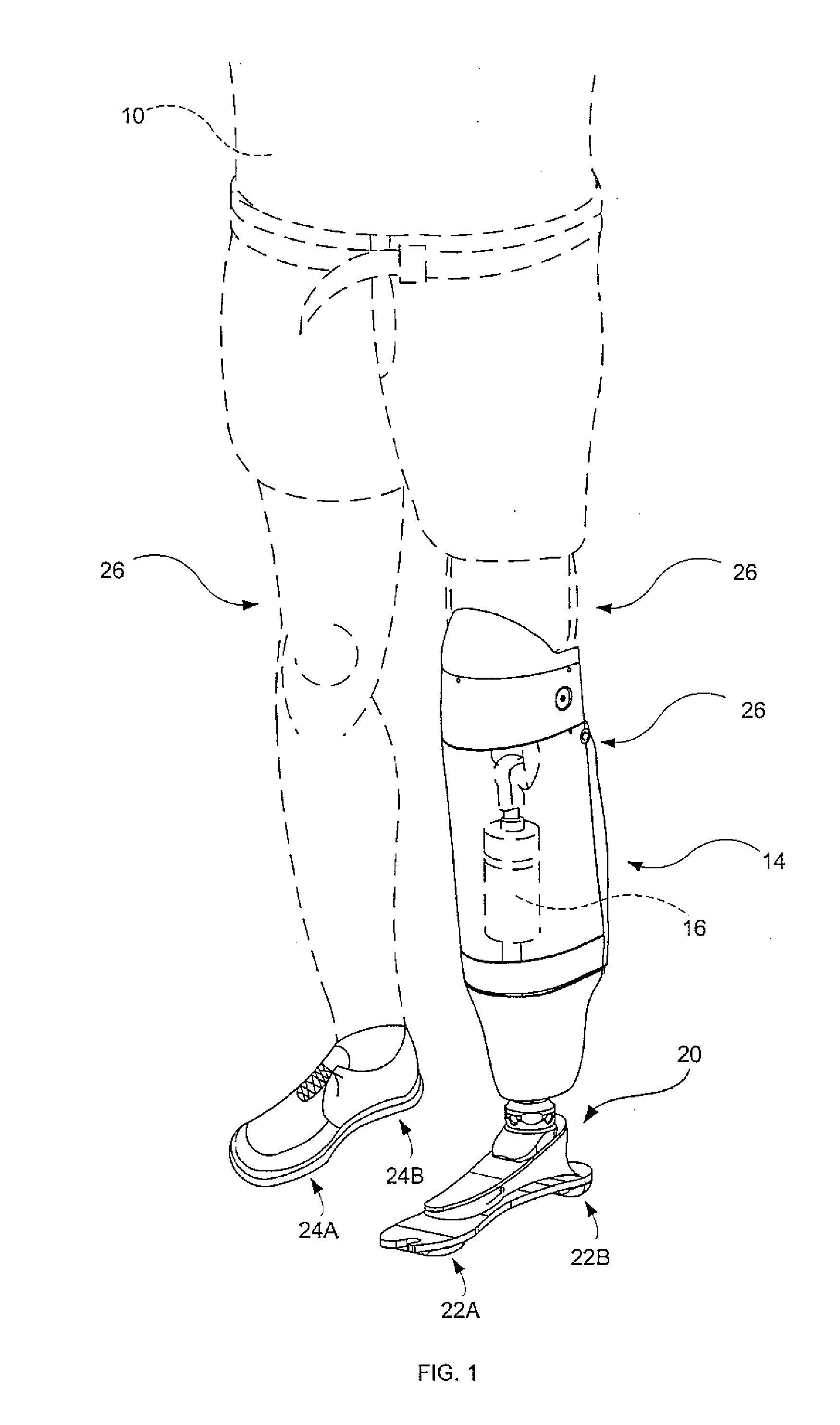
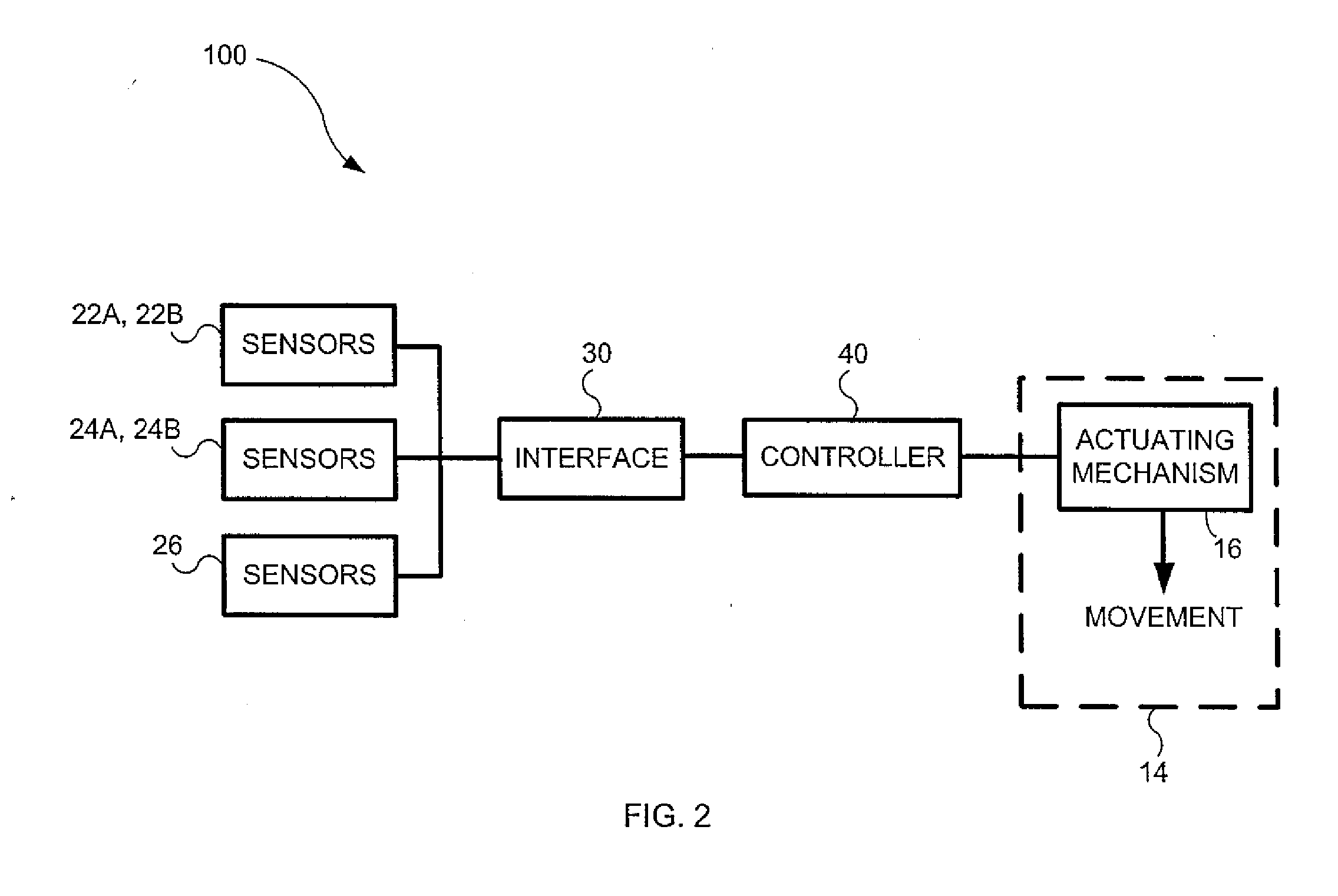
[0024]The appended figures show a instrumented prosthetic foot (20) having sensors (22A, 22B) for use, in cooperation with possible additional sensors (24A, 24B, 26), with a control system (100) for controlling a prosthesis (14) having an actuating mechanism (16). It should be understood that the present invention is not limited to the illustrated implementation since various changes and modifications may be effected herein without departing from the scope of the appended claims.
[0025]Referring therefore to FIG. 1 an individual (10) has a pair of legs (26) and (28), one of which, (26), is amputated above the knee. A prosthesis (14) is attached to the leg (26) and includes an actuating mechanism (16), which may be either passive or active. An instrumented prosthetic foot (20) is attached to the prosthesis (14) and includes sensors (22A, 22B). Additional sensors (24A, 24B) are located on the healthy foot and additional sensors (26) located on the individual (10) and / or the prosthesis ...
PUM
 Abstract
Description
Claims
Application Information