Fracture testing apparatus and method

a technology of fracture testing and apparatus, applied in the field of systems and methods for testing drilling fluid, can solve the problems of reducing the permeability of the formation, becoming difficult to remove, and prone to extreme damage in formations

Inactive Publication Date: 2011-06-02
MI
View PDF14 Cites 20 Cited by
  • Summary
  • Abstract
  • Description
  • Claims
  • Application Information

AI Technical Summary

Benefits of technology

This patent relates to a way to determine how well a drilling fluid is controlling its own leakage during use. A special testing process involves adding a substance that helps prevent leaks into a tank containing water or other liquid. Then, we measure how much liquid passes through a small opening in the tank while it's being forced out under pressure. By doing this, we can better evaluate the effectiveness of different materials used in drilling fluids.

Problems solved by technology

The problem addressed in this patent text relates to finding ways to evaluate and optimize drilling fluids and fluid loss control materials before they are used in actual drilling operations. Specifically, there is a need for reliable tools and techniques to simulate inducing fractures in permeable and impermeable formations without requiring expensive and time-consuming large-scale core testing.

Method used


Image

  • Fracture testing apparatus and method
  • Fracture testing apparatus and method
  • Fracture testing apparatus and method

Examples


example 1

[0059]Fracture tests using the systems and methods disclosed herein were focused to evaluate, inter alia, the sealing performance of a cellulosic fluid loss control material. Data was evaluated with respect to test fluid pressure, conduction loss, and fracture size.

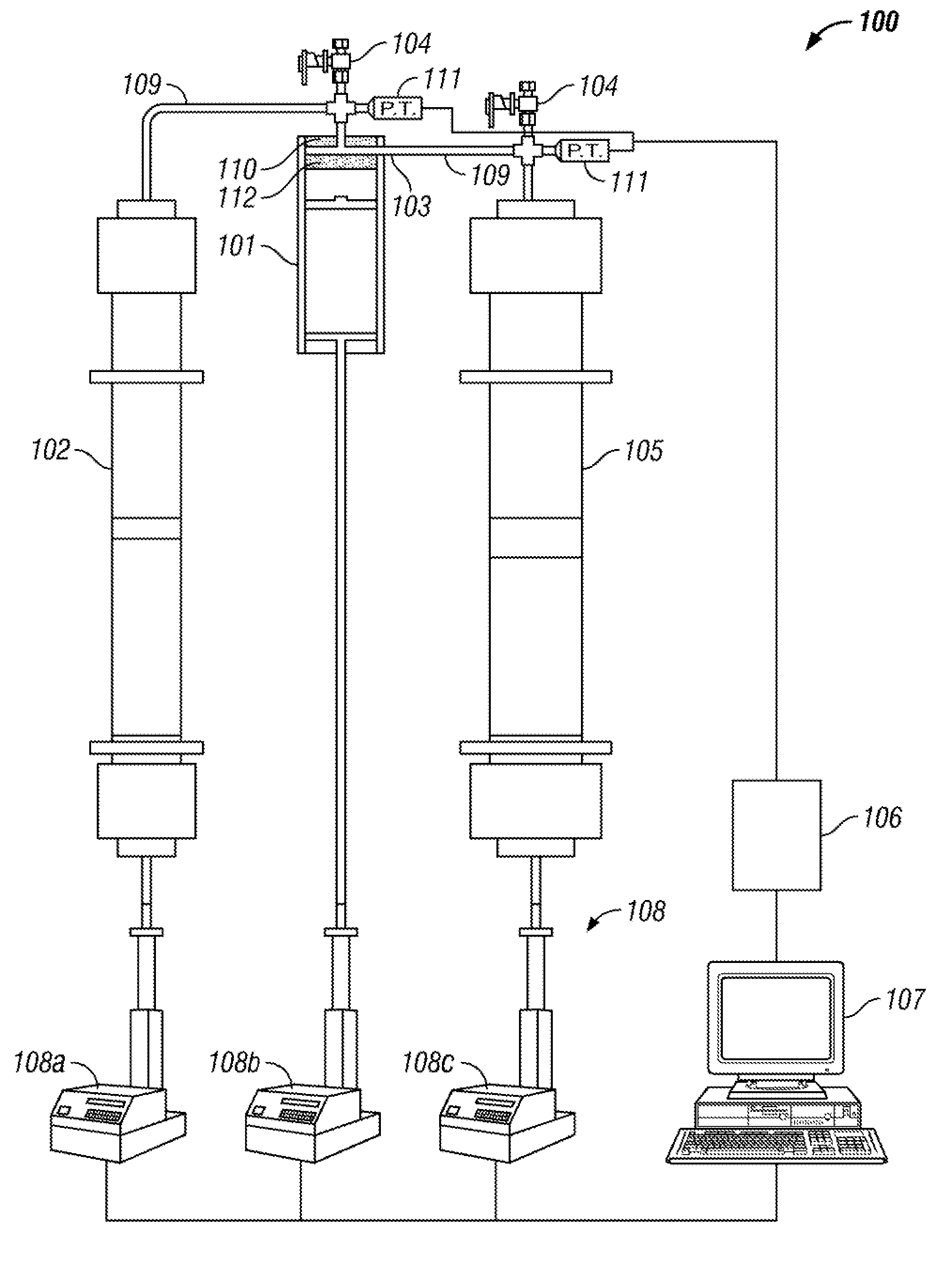
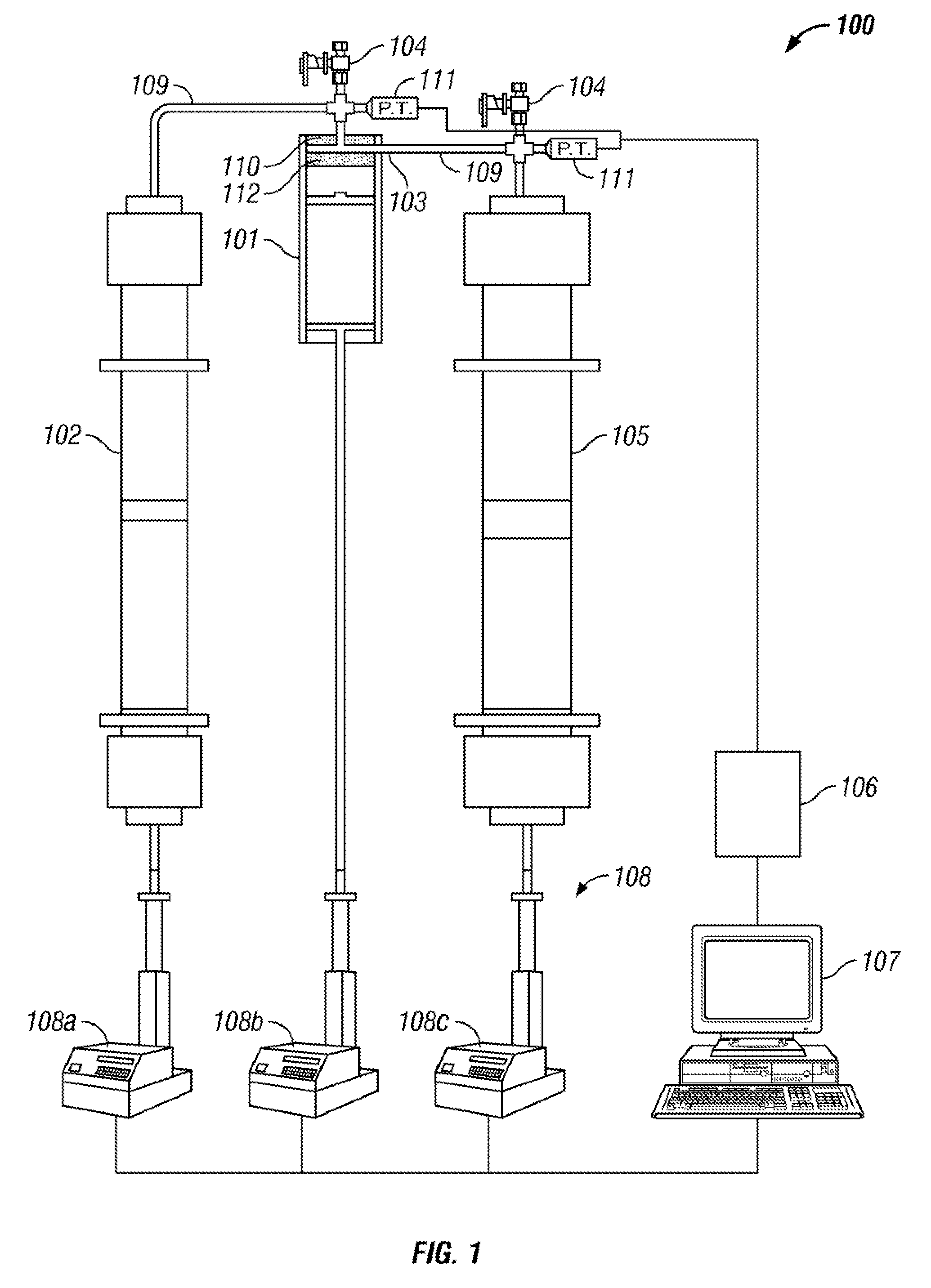
[0060]Under typical test conditions starting with an initial fracture size of 530 microns, a constant flow rate of test fluid was injected to the vessel. The testing followed in accordance to the methods of testing fluids described in detail above. Briefly, a test fluid was pumped from a test fluid container to a vessel having two opposed platens disposed therein with a minimum initial gap representative of a fracture therebetween. The test fluid continued to flow through the vessel allowing fracture tip fluid to exit the vessel by flowing into a collection container. During the test, the pressures, and other variables effecting the test were recorded by a data acquisition system and transmitted to a computer. The compute...

example 2

[0063]Fracture tests using the systems and methods disclosed herein were focused to evaluate, inter alia, the sealing performance of barite as a fluid loss control material. Data was evaluated with respect to test fluid pressure, conduction loss, and fracture size.

[0064]Under typical test conditions starting with an initial fracture size of 280 microns, a constant flow rate of test fluid was injected to the vessel. The testing followed in accordance to the methods of testing fluids described in detail above.

[0065]Referring to FIG. 8, a visual representation of a the data collected during a test of a fluid in accordance with embodiments of the present disclosure is shown. The following test includes an analysis of test fluid pressure (“mud pressure”) 600, mud volume to tip (“conductivity loss”) 602, fracture width 604.

[0066]Mud pressure 600 increased relatively quickly at the beginning of the test indicating a fast forming seal was created. As previously discussed regarding conductiv...


PUM


Abstract

An apparatus for testing a drilling fluid includes a vessel having a fluid inlet, a fluid outlet, and a pair of opposed impermeable platens disposed within the vessel. The apparatus further includes a test fluid container in fluid communication with the fluid inlet, and a collection container in fluid communication with the fluid outlet. Additionally, the system includes a data acquisition device configured to receive data from at least one of the vessel, the test fluid container, and the collection container. Also, a method for determining sealing characteristics of a drilling fluid includes injecting a test fluid having a fluid loss control material from a test fluid container to a vessel, the vessel having a first impermeable platen and a second impermeable platen with a gap between the two platens. The methods further includes measuring a fracture tip fluid loss through the gap.

Description


Claims


Application Information

Patent Timeline
Owner MI
Why Eureka
Try Eureka