
Apparatus and method for producing a concrete foundation

a technology of concrete and apparatus, applied in the field of concrete foundations, can solve the problems of inability to reuse, flanges that cannot fit onto bolts, and the surface of concrete on which the structure is mounted is typically of a certain roughness

Inactive Publication Date: 2011-06-09
GENERAL ELECTRIC CO
View PDF15 Cites 42 Cited by
  • Summary
  • Abstract
  • Description
  • Claims
  • Application Information

AI Technical Summary

Problems solved by technology

In some cases, even if the geometrical arrangement of the bolts deviates only by some millimeters from the nominal arrangement, the flange might not fit onto the bolts because the bolts cannot be pushed through the through holes in the flange.
This is undesirable, as the concrete foundation with the integrated bolts might have to be destroyed and reconstructed in this case.
If, for example, a bolt is not fixed tightly enough to the anchor ring, its upper end may tilt from a vertical direction, which is undesirable for the reasons laid out above.
However, this method is time consuming and the columns are usually buried in the concrete during casting, which means they cannot be reused.
Further, when casting a conventional foundation, the surface of the concrete on which the structure is mounted is typically of a certain roughness.
This roughness can cause gaps between the foundation and the mounted structure, which is undesirable.

Method used


Image

  • Apparatus and method for producing a concrete foundation
  • Apparatus and method for producing a concrete foundation
  • Apparatus and method for producing a concrete foundation

Examples


Embodiment Construction

Reference will now be made in detail to the various embodiments of the invention, one or more examples of which are illustrated in the figures. Each example is provided by way of explanation of the invention, and is not meant as a limitation of the invention. For example, features illustrated or described as part of one embodiment can be used on or in conjunction with other embodiments to yield yet a further embodiment. It is intended that the present invention includes such modifications and variations.

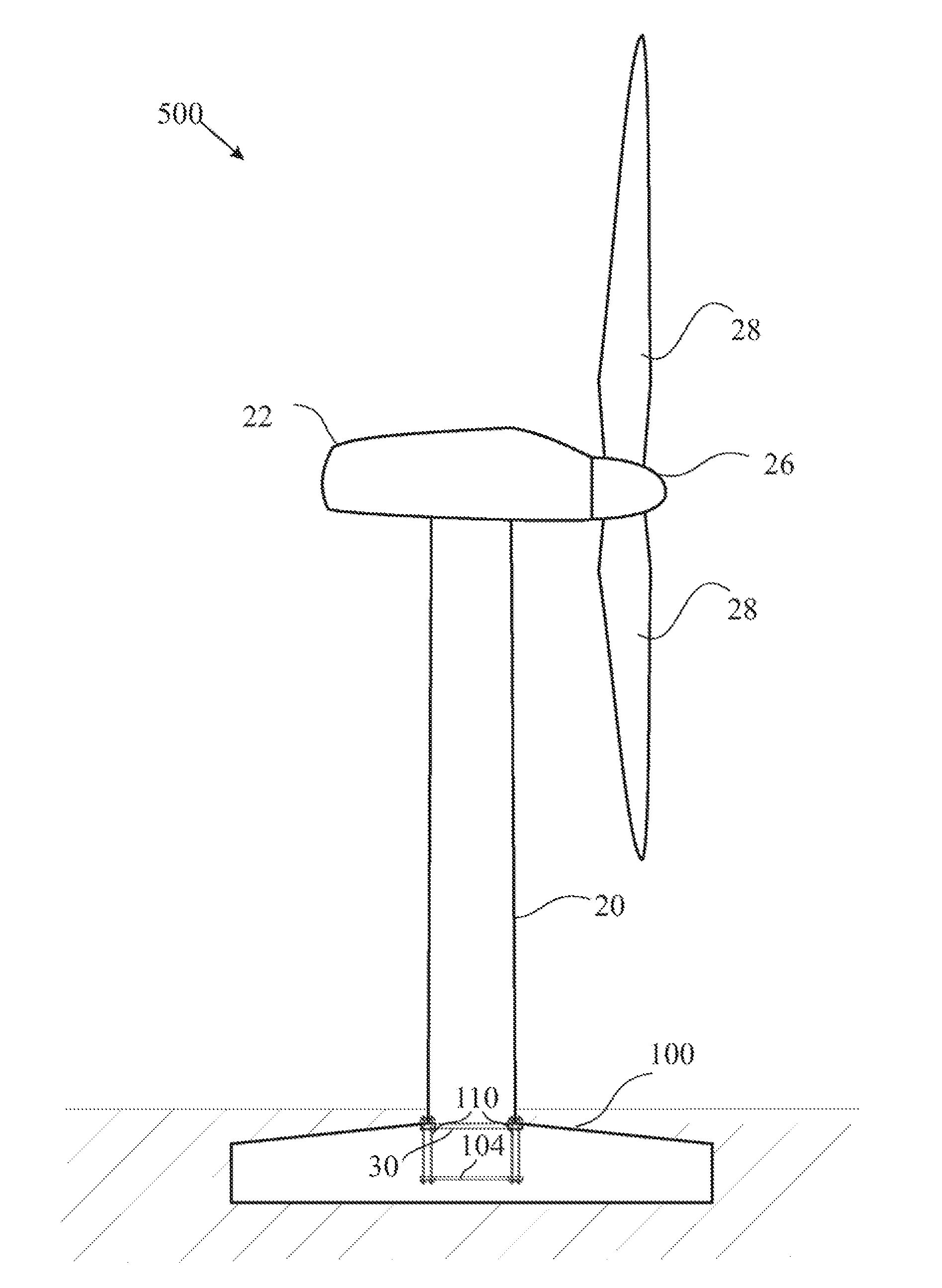
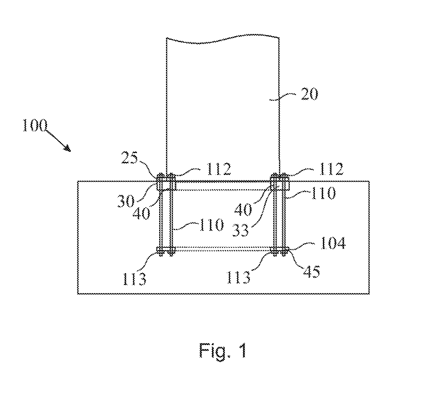
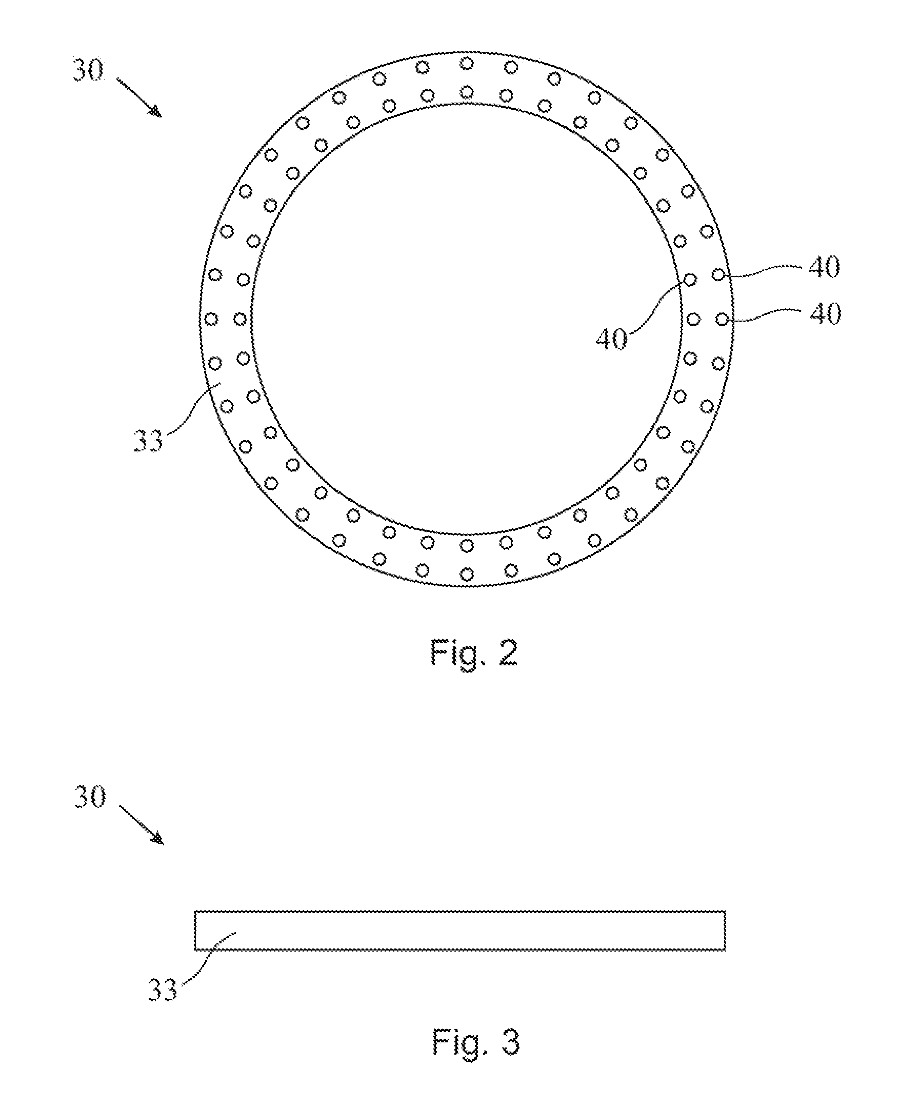
FIG. 1 shows a sectional view of an embodiment of a concrete foundation 100 for the support of a structure 20, including a foundation interface 30. The foundation interface includes a prefabricated concrete element 33. It has a plurality of through holes 40, which are geometrically arranged to correspond to an arrangement of holes or through holes 25 of the structure 20 to be supported. Cast into concrete foundation 100 is also an anchor element 104, which may also include a pluralit...


PUM


Abstract

A foundation interface for a concrete foundation for the support of a structure comprises a prefabricated concrete element with a plurality of through holes, which are geometrically arranged to correspond to an arrangement of holes or bolts of a structure to be supported. Further, a method for fabricating a concrete foundation comprising such a foundation interface is provided.

Description

BACKGROUND OF THE INVENTIONThe present disclosure relates to concrete foundations and, in particular, to concrete foundations for the support of tall, heavy or large structures like towers. More particularly, it relates to a prefabricated foundation element for a foundation. Specifically, it relates to a prefabricated foundation element for the foundation for the support of a wind turbine.To mount structures on their respective foundations, e.g. towers and the like, which may be used to support power lines, communication systems, street lighting and street signals, bridge supports, commercial signs, freeway signs, ski lifts, wind turbines, and the like, often a plurality of steel bolts are used which protrude from a face of the foundation. The bolts are used to mount a flange of the structure thereon, the flange being provided with through holes, through which the bolts are pushed during mounting of the flange to the structure. These bolts are typically arranged in a circle or recta...

Claims


Application Information

Patent Timeline
IPC IPC(8): F03D11/04E02D27/32E04B1/16
CPCE02D27/42Y02E10/728F05B2240/912F03D11/045F03D13/22E02D27/425Y02P70/50Y02E10/72
Inventor VOSS, STEFANSCHWEDE, STEFANPAURA, INGO
Owner GENERAL ELECTRIC CO
Features
  • Generate Ideas
  • Intellectual Property
  • Life Sciences
  • Materials
  • Tech Scout
  • Unparalleled Data Quality
  • Higher Quality Content
  • 60% Fewer Hallucinations
Learn More