
Pre-cast concrete veneer system with insulation layer

a veneer system and pre-cast concrete technology, applied in the field of veneer systems, can solve the problems of difficult installation of a wall or surface, high labor intensity, and difficulty in ensuring the appearance of the wall, and achieve the effect of convenient fixing to the wall or surfa

Inactive Publication Date: 2010-01-19
NASVIK PAUL C
View PDF21 Cites 42 Cited by
  • Summary
  • Abstract
  • Description
  • Claims
  • Application Information

AI Technical Summary

Benefits of technology

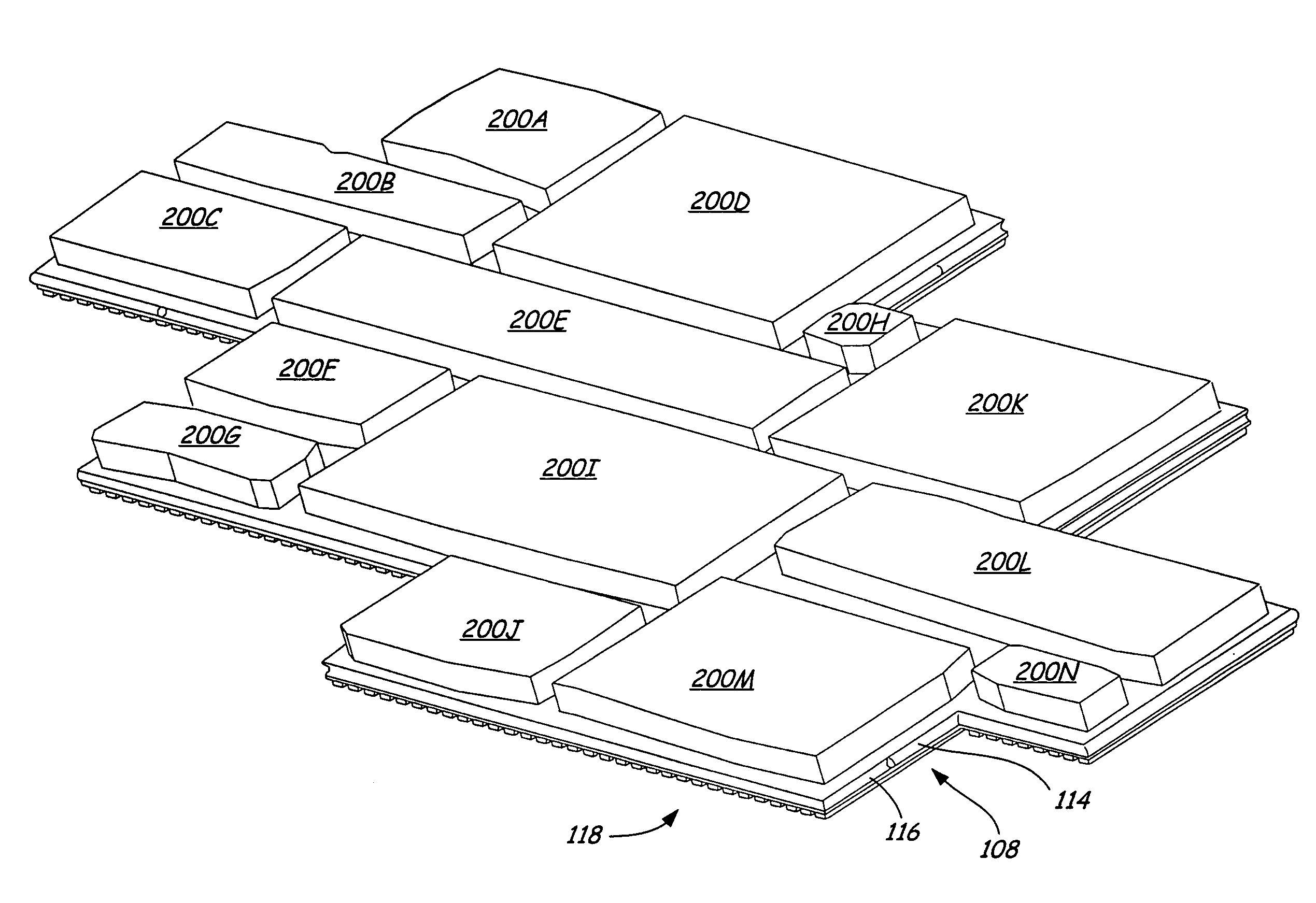
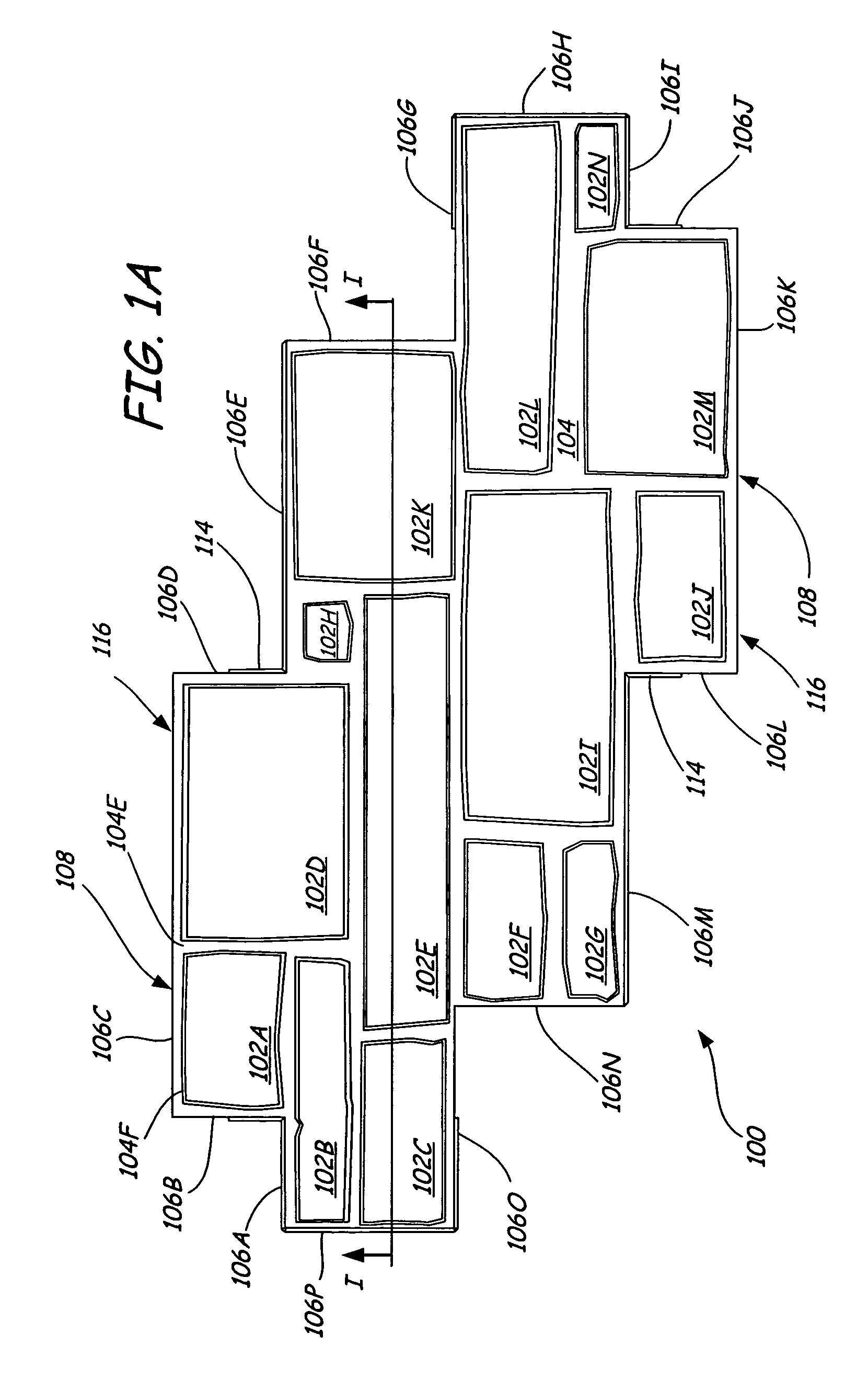
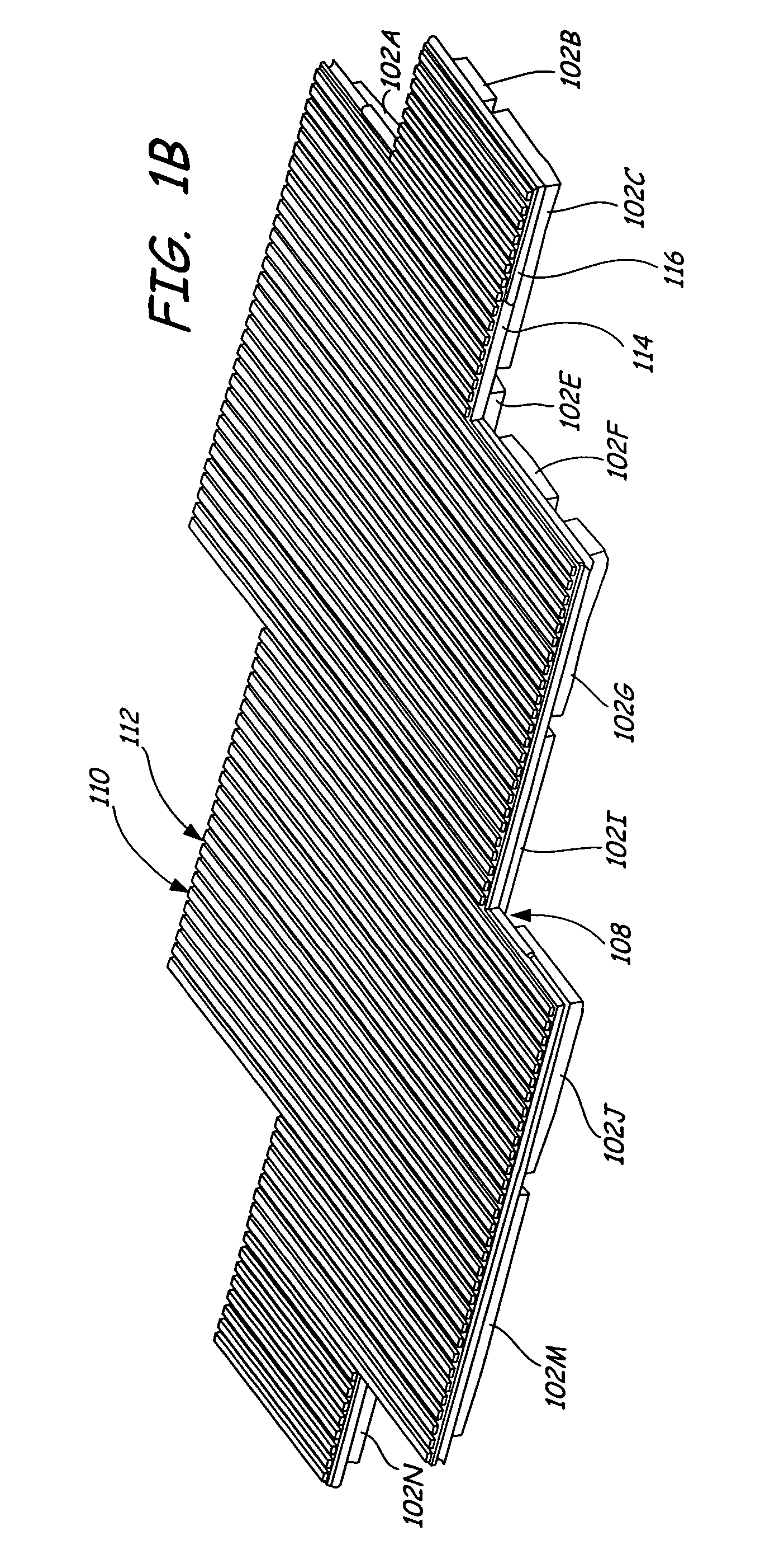
"The present invention is a multi-layered veneer panel that includes a thin concrete layer and a foam layer. The panel has an edge perimeter region that connects adjacent panels. The invention also includes a method for making the panel and installing it on a wall or surface using a special fastener. The technical effect of the invention is to provide a durable and visually appealing panel for use in building exteriors that can withstand weather and other environmental factors."

Problems solved by technology

However, building such a wall using either natural or cut stones is not always a practical option.
Constructing a wall made of stone is often very expensive, labor intensive, and requires highly skilled laborers.
Pour in place applications have problems associated with making the wall look natural.
Poured in place walls are also extremely heavy, are not useable in a wide variety of applications, and require special equipment and skilled labor to install.
Precast walls have similar repetitive pattern and seam problems as do pour in place walls.
These walls are also extremely heavy and require skilled labor and special equipment.
However, many of these veneer systems, particularly those made of vinyl products, are not realistic in texture or appearance.
In addition, the same problems arise in the inability to create a random pattern of unique stones using a minimum number of veneer panels.
Veneer systems are particularly susceptible to “paneling out”, wherein it becomes obvious that the pattern is repeating and non-random.
However, forming a veneer system using concrete has been impractical to date.
In particular, concrete veneers may be thick, making them heavy, unwieldy and difficult to install.
In addition, when made thin enough to be more practical, the concrete may crack or break easily, such as during shipping or during the installation process.
As demonstrated, existing systems, both using and not using concrete for simulating exterior finishes, have several problems associated with them.
In a simulated stone wall it is difficult to ensure that the pattern appears random and non-repetitive.
This, however, increases cost and labor.
Increasing the variety of patterns can be expensive.
In pour in place and precast wall systems, the solid concrete walls are heavy and require skilled labor and special equipment to install.

Method used


Image

  • Pre-cast concrete veneer system with insulation layer
  • Pre-cast concrete veneer system with insulation layer
  • Pre-cast concrete veneer system with insulation layer

Examples


first embodiment

[0058]Foam layers 708A, 708B also provide an easily shapable, lightweight material for forming other features that enhance multi-layered panels 700A, 700B. The back side of foam layers 708A, 708B can also have ribs and grooves as described in the first embodiment, shown in FIG. 6, to facilitate air flow between the multi-layered panels 708A, 708B and the surface to which it will be applied.

[0059]On row 701DA of multi-layered panel 700A, the second portion 716A of foam layer 708A extends beyond concrete layer 706A a uniform width to form slat 710D. On rows 701EB, 701FB, 701GB, 701HB of multi-layered panel 700B, the second portion 716B of foam layer 708B extends beyond concrete layer 706B a uniform width to form slats 710E, 710F, 710G, 710H. On row 701HA of multi-layered panel 700A, the first portion 714A of foam layer 708A extends beyond the second portion 716A to form a first void 720. On rows 701EB, 701FB, 701GB, 701HB of multi-layered panel 700B, the first portion 714B of foam lay...

third embodiment

[0061]FIG. 8A shows multi-layered panel 800 for use in a veneer system. In this embodiment multi-layered panel 800 simulates lap siding. Multi-layered panel 800 can have many variations in the configuration of the lap siding. In the embodiment shown, multi-layered panel 800 comprises two offset rows of lap siding 820, 822. In other embodiments multi-layered panel 800 can have only one row of lap siding. One benefit of having offset rows 820, 822 is to facilitate alignment of multiple multi-layered panels 800 during installation of the veneer system.

[0062]Multi-layered panel 800 comprises a concrete layer 802 and a foam layer 804. The layers of this embodiment of the invention are similar to that of the first and second embodiments. The manufacturing of multi-layered panel 800 is also similar to that of the first and second embodiment. Concrete layer 802 is a thin uniformly thick layer that is cast onto foam layer 804. Thus, foam layer 804 completely fills in the back side of concret...


PUM

PropertyMeasurementUnit
widthaaaaaaaaaa
widthaaaaaaaaaa
thickaaaaaaaaaa

Abstract

A multi-layered panel comprises a first layer made of concrete, a second layer made of foam and an edge perimeter region. The first layer is a thin concrete layer of near uniform thickness that is cast onto the second layer. The exterior surface of the concrete layer simulates an exterior surface of a building. The front of the foam layer has dimensions designed to accommodate the application of the concrete layer. The back of the foam layer has features that assist in mounting the panel on an exterior surface of a building. The edge perimeter region includes a system for interconnecting adjacent multi-layered panels.

Description

BACKGROUND OF THE INVENTION[0001]The present invention relates to veneer systems for finishing the exterior appearance of walls. In particular, the present invention relates to concrete and foam layered veneer panels which can be inexpensively and easily installed to form a wall facade which resembles a wall made from a more expensive and more difficult to install material, such as stone, brick or wood.[0002]Many types of materials are used to form the exterior finish of buildings. Many factors go into choosing the exterior finish for each building, including appearance, cost, ease of installation, durability and insulating capacity. Stone, brick and wood finishes are popular due to their aesthetic appearance and durability. In particular, cut stone, natural stone, brick, log siding, shingle siding, and lap siding are examples of systems used as exterior finishes for building walls.[0003]Stone walls are particularly pleasing because of the unique appearance of each stone and the ran...

Claims


Application Information

Patent Timeline
Patent Type & Authority Patents(United States)
IPC IPC(8): E04F13/08
CPCB32B3/06B32B3/085B32B3/263B32B3/30B32B13/02B32B13/04B32B13/045B32B2307/718B32B2419/04B32B2607/00
Inventor NASVIK, PAUL C.
Owner NASVIK PAUL C
Learn More