Pre-cast concrete veneer system with insulation layer

Inactive Publication Date: 2006-07-20
NASVIK PAUL C
View PDF21 Cites 50 Cited by
  • Summary
  • Abstract
  • Description
  • Claims
  • Application Information

AI Technical Summary

Benefits of technology

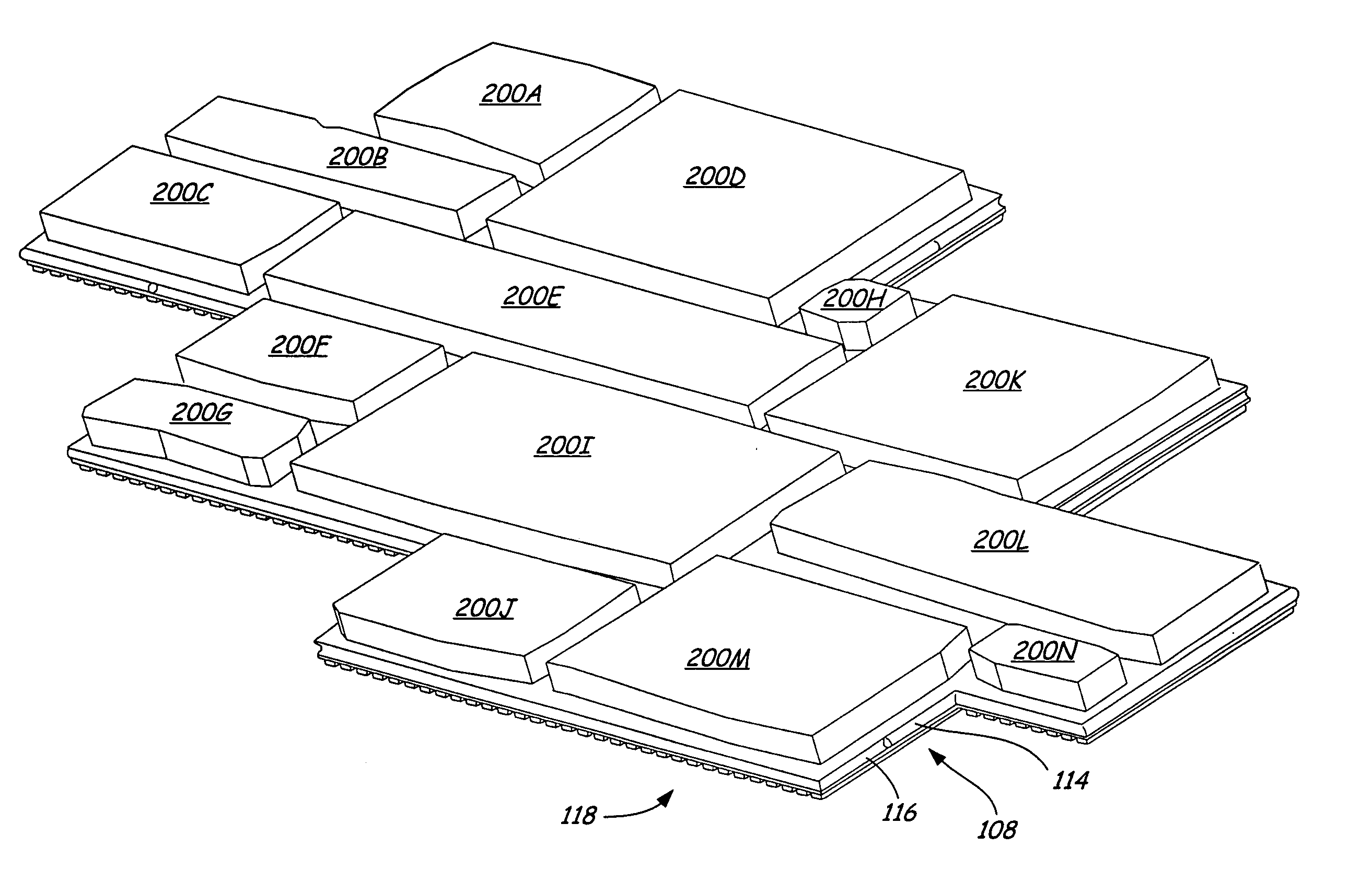
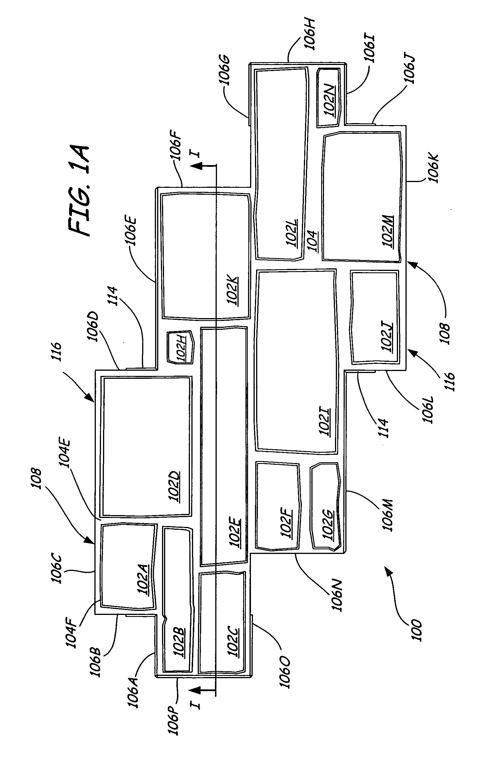
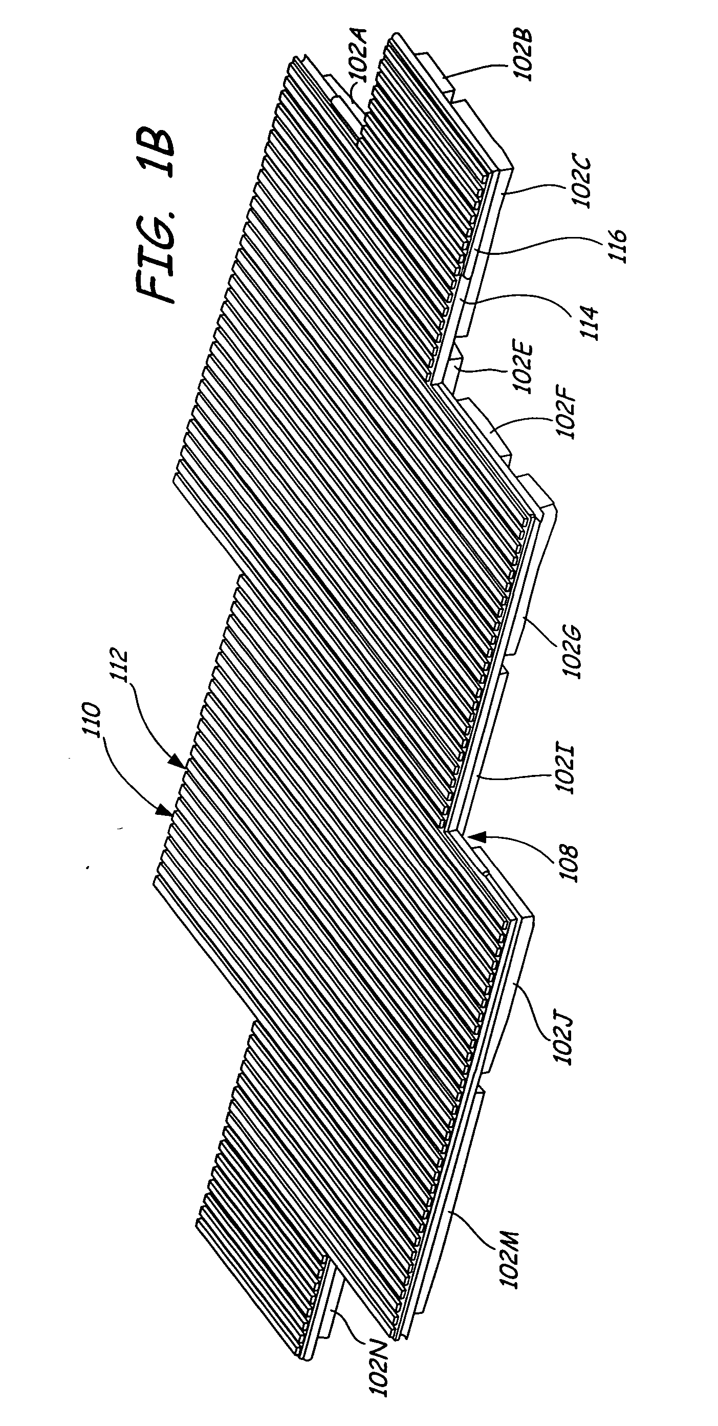
[0012] The present invention comprises a multi-layered veneer panel. The multi-layered panel comprises a first layer made of concrete, a second layer made of foam and an edge perimeter region. The first layer is a thin concrete layer of near uniform thickness that is cast onto the second layer. The exterior surface of the concrete layer simulates an exterior surface of a building. The front of the foam layer has dimensions designed to accommodate the application of the concrete layer. The back of the foam layer has features that assist in mounting

Problems solved by technology

However, building such a wall using either natural or cut stones is not always a practical option.
Constructing a wall made of stone is often very expensive, labor intensive, and requires highly skilled laborers.
Pour in place applications have problems associated with making the wall look natural.
Poured in place walls are also extremely heavy, are not useable in a wide variety of applications, and require special equipment and skilled labor to install.
Precast walls have similar repetitive pattern and seam problems as do pour in place walls.
These walls are also extremely heavy and require skilled labor and special equipment.
However, many of these veneer systems, particularly those made of vinyl products, are not realistic in texture or appearance.
In addition, the same problems arise in the inability to create a random pattern of unique stones using a minimum number of veneer panels.
Veneer systems are particu

Method used


Image

  • Pre-cast concrete veneer system with insulation layer
  • Pre-cast concrete veneer system with insulation layer
  • Pre-cast concrete veneer system with insulation layer

Examples


Example

[0054]FIG. 7A shows a front view of a second embodiment of the multi-layered panel 700 for use in a veneer system. In this embodiment multi-layered panel 700 has a simulated brick finish. Multi-layered panel 700 is comprised of a foam layer and a concrete layer similar to that of multi-layered panel 100 of the first embodiment. Simulated bricks 702A-702X are made up of raised regions. Simulated mortar 704 fills in the area between the bricks 702A-702X. Multi-layered panel 700 comprises eight rows of three bricks. Each row is offset by one half the length of one brick, creating a protruding row of bricks at the end of each row. A first set of rows 701A, 701B, 701C, 701D including the top row, protrude to the right. A second set of rows 701E, 701F, 701G, 701H protrude to the left. Every multi-layered panel 700 in an installed veneer system is identical. They are designed to be placed in the same orientation directly next to and on top of each other. Multi-layered panel 700 of this emb...

Example

[0061]FIG. 8A shows a third embodiment of multi-layered panel 800 for use in a veneer system. In this embodiment multi-layered panel 800 simulates lap siding. Multi-layered panel 800 can have many variations in the configuration of the lap siding. In the embodiment shown, multi-layered panel 800 comprises two offset rows of lap siding 820, 822. In other embodiments multi-layered panel 800 can have only one row of lap siding. One benefit of having offset rows 820, 822 is to facilitate alignment of multiple multi-layered panels 800 during installation of the veneer system.

[0062] Multi-layered panel 800 comprises a concrete layer 802 and a foam layer 804. The layers of this embodiment of the invention are similar to that of the first and second embodiments. The manufacturing of multi-layered panel 800 is also similar to that of the first and second embodiment. Concrete layer 802 is a thin uniformly thick layer that is cast onto foam layer 804. Thus, foam layer 804 completely fills in ...


PUM

PropertyMeasurementUnit
Thicknessaaaaaaaaaa
Lengthaaaaaaaaaa
Lengthaaaaaaaaaa

Abstract

A multi-layered panel comprises a first layer made of concrete, a second layer made of foam and an edge perimeter region. The first layer is a thin concrete layer of near uniform thickness that is cast onto the second layer. The exterior surface of the concrete layer simulates an exterior surface of a building. The front of the foam layer has dimensions designed to accommodate the application of the concrete layer. The back of the foam layer has features that assist in mounting the panel on an exterior surface of a building. The edge perimeter region includes a system for interconnecting adjacent multi-layered panels.

Description

BACKGROUND OF THE INVENTION [0001] The present invention relates to veneer systems for finishing the exterior appearance of walls. In particular, the present invention relates to concrete and foam layered veneer panels which can be inexpensively and easily installed to form a wall facade which resembles a wall made from a more expensive and more difficult to install material, such as stone, brick or wood. [0002] Many types of materials are used to form the exterior finish of buildings. Many factors go into choosing the exterior finish for each building, including appearance, cost, ease of installation, durability and insulating capacity. Stone, brick and wood finishes are popular due to their aesthetic appearance and durability. In particular, cut stone, natural stone, brick, log siding, shingle siding, and lap siding are examples of systems used as exterior finishes for building walls. [0003] Stone walls are particularly pleasing because of the unique appearance of each stone and t...

Claims


Application Information

Patent Timeline
IPC IPC(8): B27K1/00
CPCB32B3/06B32B3/085B32B3/263B32B3/30B32B13/02B32B13/04B32B13/045B32B2307/718B32B2419/04B32B2607/00
Inventor NASVIK, PAUL C.
Owner NASVIK PAUL C
Why Eureka
Try Eureka