Heat transfer device

Inactive Publication Date: 2019-08-15
JOINSET
View PDF3 Cites 0 Cited by
  • Summary
  • Abstract
  • Description
  • Claims
  • Application Information

AI Technical Summary

Benefits of technology

[0021]Therefore, since thermally conductive double-sided adhesive tape or a thermally conductive adhesive is not additionally used to fix the heat transfer device to an accommodation groove of a metal case, the heat transfer device may be easily fixed and densely installed even in a small space. Thus, the heat transfer device is economical.
[0022]In addition, since the contact area between the heat transfer device

Problems solved by technology

In addition, as the size of products decreases, heat is more densely generated.
Therefore, if a heat pipe has a complex shape such as a bent shape and a large length, it is difficult to manufacture double-sided adhesive tape according to the shape of the heat pipe, and it is more difficult to manufacture double-side adhesive tape having a small thickness or a long length according to the shape of an accommodation groove to install the heat pipe in the accommodation groove.
In addition, since double-sided adhesive tape is additionally used to fix such a heat

Method used


Image

  • Heat transfer device
  • Heat transfer device
  • Heat transfer device

Examples


Example

[0030]Technical terms used herein are only for explaining specific embodiments while not limiting the present invention. In addition, unless otherwise defined, technical terms used herein have the same meaning as commonly understood by those of ordinary skill in the art and will not be interpreted in an overly broad or narrow sense. In addition, if technical terms used herein are incorrect to exactly express the idea of the present invention, the technical terms should be interpreted as terms by which those of ordinary skill in the art can correctly understand the idea of the present invention. In addition, general terms used herein may be interpreted as defined in dictionaries or according to the contextual meanings, and should not be interpreted in an overly narrow sense.

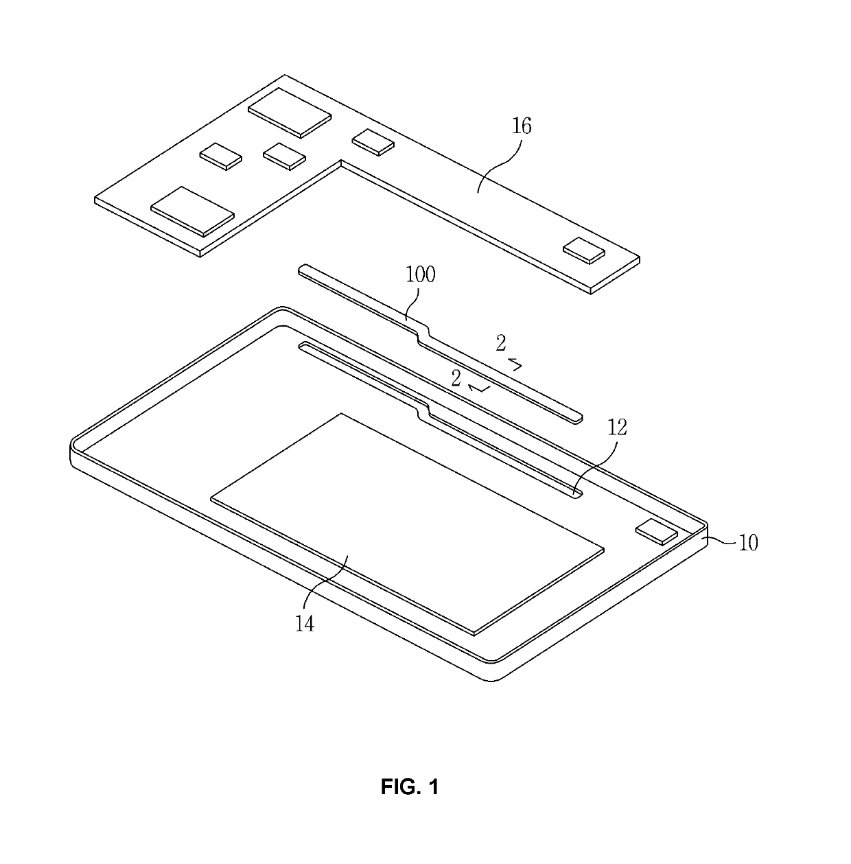
[0031]FIG. 1 illustrates a state in which a heat pipe 100 is applied to a smartphone according to an embodiment of the present invention.

[0032]A battery 14 may be provided on a back cover 10 of the smartphone, and...


PUM

PropertyMeasurementUnit
Lengthaaaaaaaaaa
Flexibilityaaaaaaaaaa
Electrical conductoraaaaaaaaaa

Abstract

A heat transfer device configured to be independently fixed and densely mounted. The heat transfer device includes: a main body formed of a metallic material and forming a tube sealed to maintain a vacuum therein; and a thermally conductive layer having elasticity and adhered around the main body.

Description

REFERENCE TO RELATED APPLICATIONS[0001]This application claims the priority benefit of Korean Patent Application No. 10-2018-0016952 filed on Feb. 12, 2018, the entire contents of which are incorporated herein by reference.FIELD OF THE INVENTION[0002]The present invention relates to a heat transfer device, and more particularly, to a heat transfer device configured to be independently fixed and easily mounted in high density.BACKGROUND OF THE INVENTION[0003]In recent years, electronic components or modules have been highly integrated and designed to have high performance, and thus more heat is generated from such electronic components or modules. In addition, as the size of products decreases, heat is more densely generated. Therefore, measures for dissipating heat become more important.[0004]This situation is more noticeable in mobile terminals such as smartphones and tablets, and direct cooling or heat transfer is necessary to handle generated heat.[0005]Heat transfer devices such...

Claims


Application Information

Patent Timeline
IPC IPC(8): F28D15/02
CPCF28D15/0241F28D15/0233F28D15/0275H05K7/20436F28F2235/00H01L21/4878H01L23/427C09D133/00C09D183/00C09J11/04C09J133/00C09J183/00C09D7/61
Inventor KIM, SUN-KI
Owner JOINSET
Why Eureka
Try Eureka