
Light guide bar and connector assembly

Active Publication Date: 2017-11-02
GIGA BYTE TECH CO LTD
View PDF2 Cites 0 Cited by
  • Summary
  • Abstract
  • Description
  • Claims
  • Application Information

AI Technical Summary

Benefits of technology

The invention is a light guide bar that can be easily set between two connectors to indicate and decorate the environment. It prevents the connectors from cracking under heavy usage. The light guide bar is positioned between the connectors and is easy to assemble. The light sources on the main board enter the guide bar to create a thin layer of light between the connectors.

Problems solved by technology

In terms of adhesion, it may be difficult to determine whether the components are properly positioned if the space is limited, and overflow of the adhesive may also occur sometimes. In terms of hot riveting, the components need to be heated to be melted and deformed so as to be combined, which may be troublesome for fabrication.
When the memory module is inserted into the memory connector on the main board, it may cause the case of the memory connector to crack.
Thus, how to prevent crack of the connector is also an issue that needs to be addressed.

Method used


Image

  • Light guide bar and connector assembly
  • Light guide bar and connector assembly
  • Light guide bar and connector assembly

Examples


Embodiment Construction

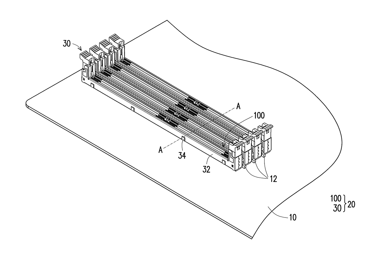
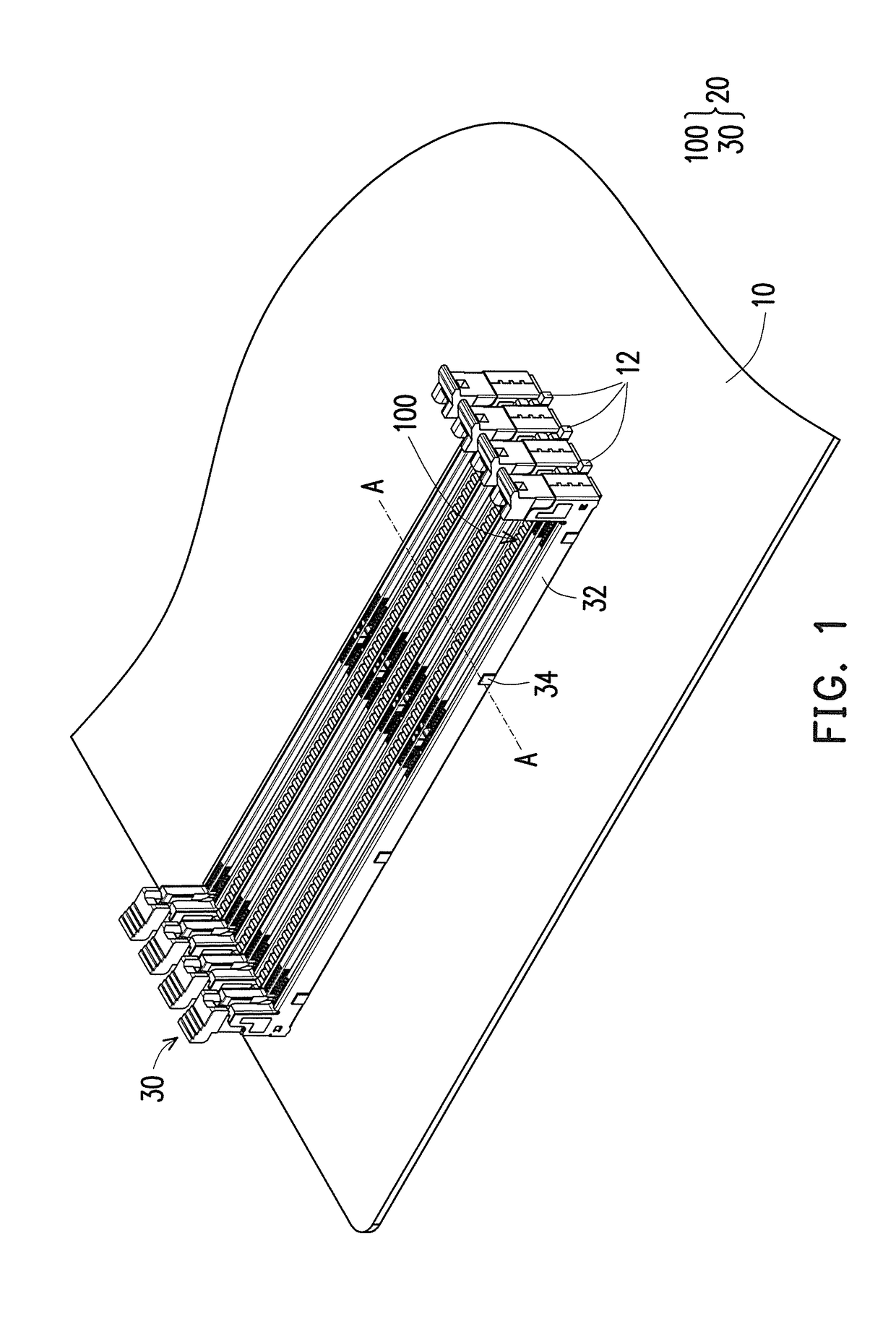
[0036]FIG. 1 is a schematic view of a connector assembly disposed on a main board according to an embodiment of the invention. Referring to FIG. 1, a connector assembly 20 of this embodiment is disposed on a main board 10 and the connector assembly 20 includes a plurality of connectors 30 that are fixed onto and electrically connected with the main board10. In this embodiment, the connector 30 is a memory module connector, for example, but the type of the connector 30 is not limited thereto.

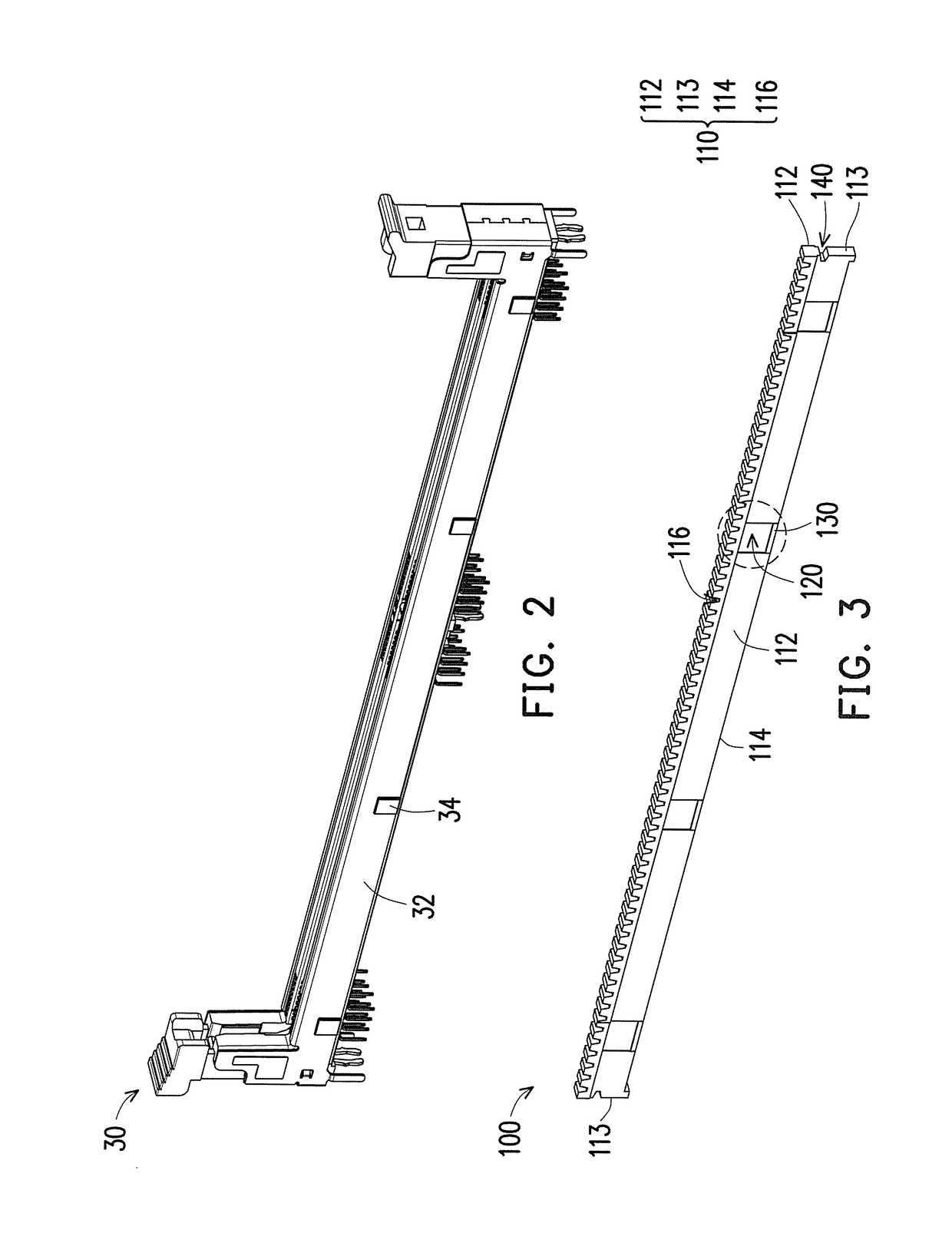
[0037]In order to guide light for the connector 30, decorate the connector 30, and reduce the possibility of crack of the connector 30, the connector assembly 20 further includes at least one light guide bar 100 so as to achieve the aforementioned functions. Details are described hereinafter.

[0038]As shown in FIG. 1, the connector assembly 20 of this embodiment includes four connectors 30 and three light guide bars 100, for example. The four connectors 30 are arranged in parallel to form three ga...


PUM


Abstract

A light guide bar adapted to be interleaved between two connectors which are disposed on a main board. Each of the connectors has a connector lateral wall. At least one connector includes a positioning protrusion. The light guide bar includes a body. The body includes two opposite light guide bar lateral walls and at least one positioning recess. Each positioning recess is formed on one of the light guide bar lateral walls. The at least one positioning recess is adapted to be positioned on the positioning protrusion of the at least one connector. A connector assembly having the light guide bar and the two connectors is further provided.

Description

CROSS-REFERENCE TO RELATED APPLICATION[0001]This application claims the priority benefits of Taiwan application serial no. 105113362, filed on Apr. 29, 2016 and Taiwan application serial no. 105119043, filed on Jun. 17, 2016. The entirety of each of the above-mentioned patent applications is hereby incorporated by reference herein and made a part of this specification.BACKGROUND OF THE INVENTIONField of the Invention[0002]The invention relates to a light guide bar and a connector assembly, and particularly to a light guide bar that can be easily fixed between two connectors and a connector assembly including the light guide bar and the two connectors.Description of Related Art[0003]Currently, screw tightening, adhesion, hot riveting and so on are common methods for fixing a component onto other components (e.g., connector) on a main board. In terms of screw tightening, it is required to respectively drill screw holes and through holes on two components and then tighten screws to fix...

Claims


Application Information

Patent Timeline
IPC IPC(8): F21S4/28F21V33/00
CPCF21V33/00F21S4/28H01R13/7172G02B6/0001G02B6/0078G02B6/0088
Inventor LAI, CHIH-MINGKAO, YUNG-SHUN
Owner GIGA BYTE TECH CO LTD
Learn More